Rivulis F2400 Media Filter
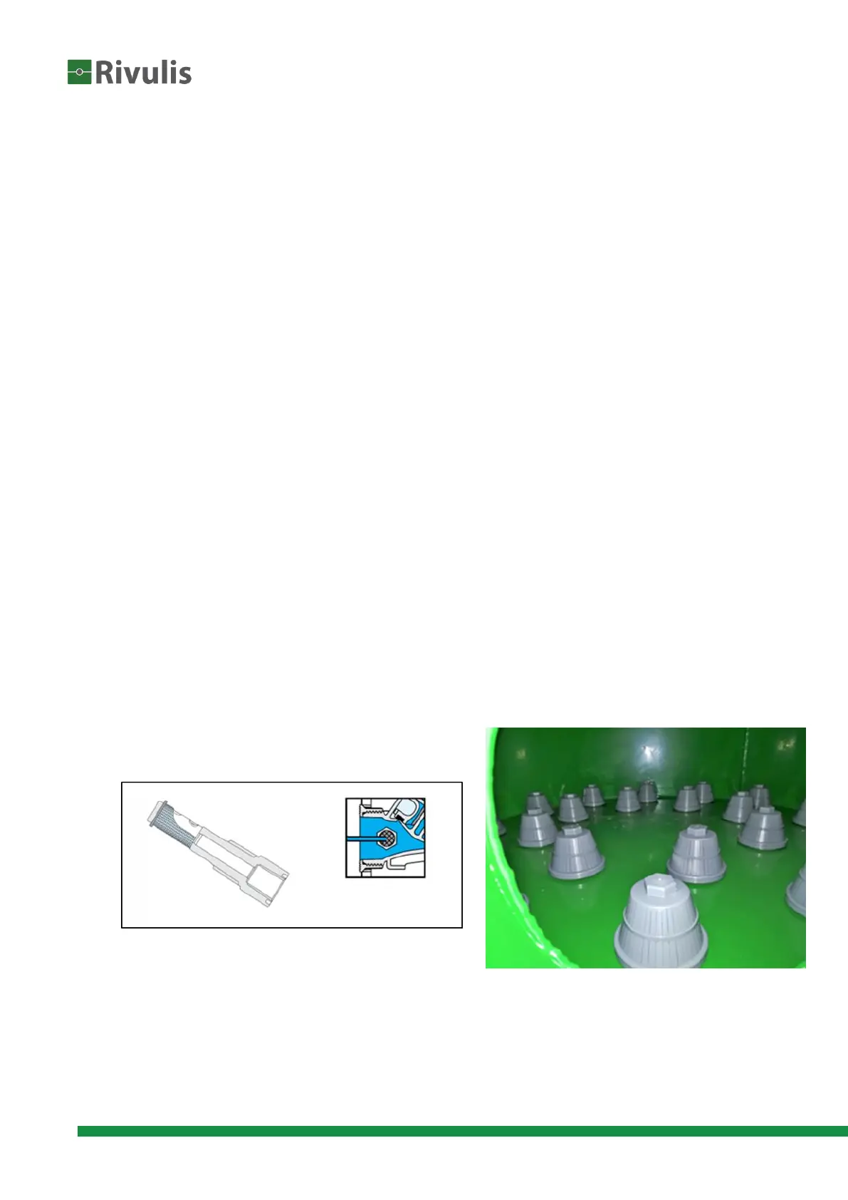
inlet manifold of the array, passing through a security filter before going into the valve’s
control chamber (Img. 1.)
Hydraulic control tubes should be as short as possible.
Using the 8mm (DN) pipe supplied, make the following connections:
Connect command pipes between solenoids and filter valves according to the assembly
diagram. (Img. 3)
The DP sensor is connected by 2 command tubes: one which comes from the filters inlet
(High pressure) will be connected to the red point, and one that comes from the outlet
(Lower pressure) will go to the black point. (Img. 4)
In an automatic filtering back flushing array, the controller should be linked according to the
scheme (whenever needed, the controller producer’s explanation pages - are available for
consultation in the “annexes”)
Check that the DP sensor is properly connected to the controller in the chip “DP Sensor”
with pin ports (Rd, Gr, Bl, Wt)
Take special care that the flow direction is correct
Having installed the array general complex, make sure that all service openings,
connections, valves and accessories are closed tightly.
In case of a DC controller, install the batteries.
Connect the filtration array inlet to the upstream water supply pipe.
Connect the filtration array outlet to the downstream water pipe.
Connect the system's backwash manifold drainage to the main drain; the main drain should
be according to the recommendation below.
Note: The length and size of the back-flush manifold drain tubing, has a significant
influence on the array’s proper operation.
Drain and vent pipes (solenoids and air valves) should be routed so that the drain will be
connected to the main drainage pipe and water will not spill on the system components.
Carefully open the inlet valve, fill up the array with water and check for leakage. Be careful
not to over-pressurize the system.
Image.1. Self-cleaning backup filter, washing valve inlet (left)
Image.2. Nozzles on reinforced steel plate board (right)
 Loading...