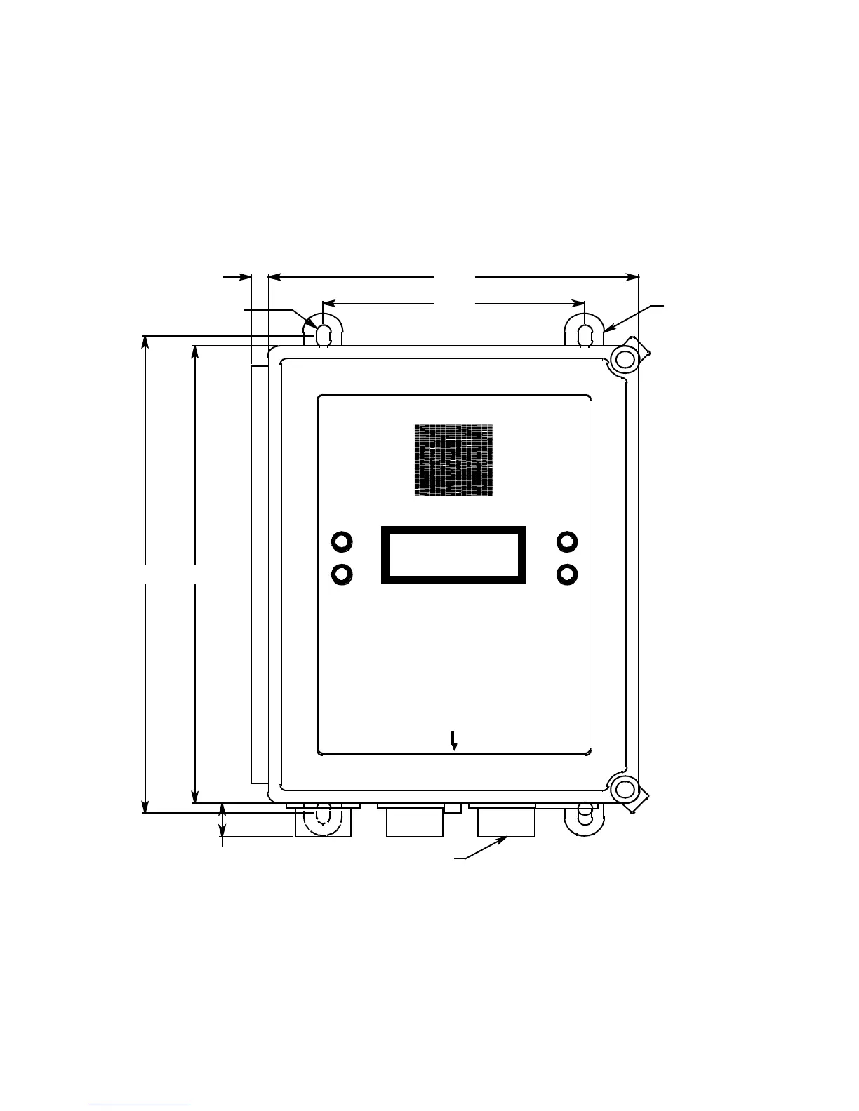
Mounting the Beacon 200 Gas Monitor • 17
5. Insert 1/4 in. or 5/16 in. screws through the slots in the mounting feet at
each corner of the housing to secure the housing to the mounting
surface (see Figure 4).
6. Each of the door clamps has a feature for locking device installation. A
locking device that requires a tool to unlock must be installed in each
door clamp.
Mounting
Feet, 4X
Ø .38 x .50 slot, 4X
.41
6.00
8.50
ALARM 2
PILOT
FAIL
RESET
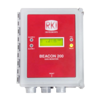
BEACON 200
GAS MONITOR
ALARM 1
10.5010.94
3/4 " Conduit Hub(3)
.80
Figure 4. Beacon 200 Gas Monitor Outline and Mounting Dimensions