26 • Wiring the Beacon 200 Gas Monitor
and the bottom one is for channel 2. See the transmitter instruction
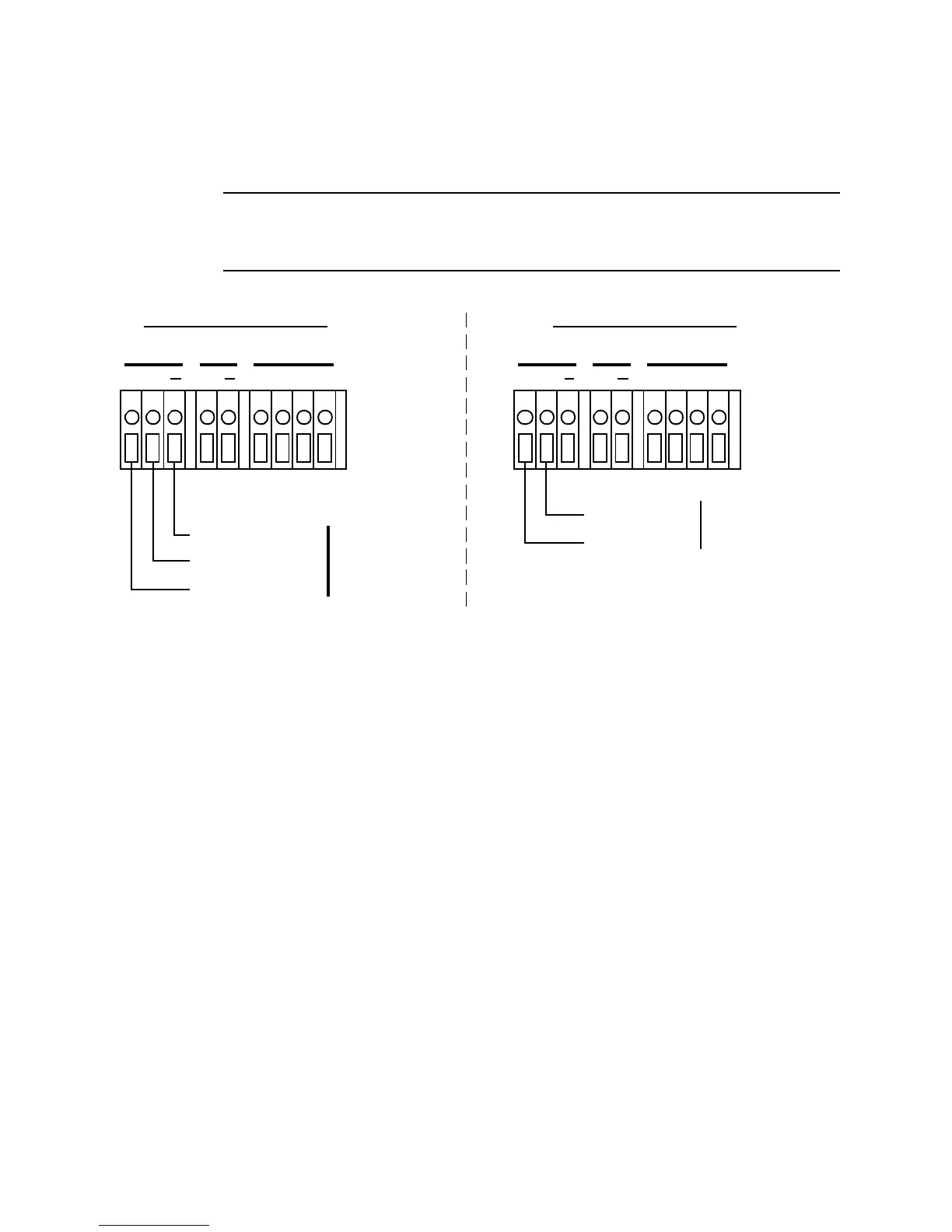
manual for controller terminal connections. Figure 10 below illustrates
typical transmitter wiring connections.
CAUTION: Do not route power and transmitter wiring through the same
conduit hub. The power wiring may disrupt the transmission of
the transmitter’s signal to the Beacon 200.
AMP/PREAMP OXYGEN
+ + S
LEL
RW G B
2-Wire 4-20 ma
Transmitter
+ 24 VDC
FB (4-20 mA)
OXYGEN
2-Wire Connection
+ S
AMP/PREAMP
+
3-Wire 4-20 ma
Transmitter
3-Wire Connection
+ 24 VDC
FB (4-20 mA)
-
(DC GROUND)
LEL
RW G B
Figure 10. Generic 4 to 20 mA Transmitter Output Wiring