Models
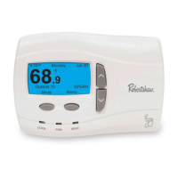
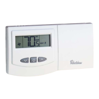
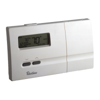
9801
i
,
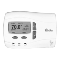
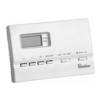
9815
i
and
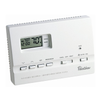
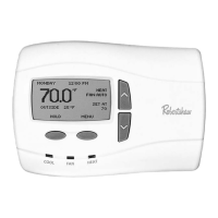
9820
i
Quick Start Installation Manual
111-321D
Installation DOs and DON’Ts
DO
• Shut off all power to system before installing.
• Read entire manual before installing.
• Make sure that all wiring conforms to
national and local codes.
DO NOT
•
Install on voltages greater than 30 VAC.
• Short jumper across terminals on the gas
valve or at the system control.
• Connect ground to any terminal in
this unit.
• Install on outside walls or in direct sunlight.
Select location for installation.
Open the case with a screwdriver. Place
in slot and gently pry forward at all four
locations.
Mark mounting hole locations on wall.
Drill
3
/
16
” holes at marked locations on
wall. Insert plastic anchors into holes.
Align unit base over plastic anchors
embedded in wall and secure with the
screws provided.
Connect wiring between unit and
furnace. For Model 9801i (1H/1C
furnace applications).
6
Cut
out
opening
a
b
1/4"
1-1/2"
1"
1
2
3
4
Mark mounting hole
locations on wall using
unit base as template.
Drill
3
/
16
holes
a
b
Press anchors into holes until flush.
Y1
R
C
E/W1
H O B G
Thermostat
C - 24VAC Common
R - 24VAC
Y1 - 1st stage cooling
E/W1 - 1st stage heating
O - Not used
B - Not used
G - Fan
H - Humidification
TERMINAL DESIGNATIONS
C
C
H
R
Y
W
G
B
O
Note: To avoid electrical problems, use the system transformer for both
the thermostat and humidifier.
9801i
Humidifier
Equipment Wiring
Terminals
Please refer to furnace
installation manual for
proper terminations
Remove 1/4” of insulation
from end of each wire
DELUXE
PROGRAMMABLE
THERMOSTATS