302 Rockwell Automation Publication 7000L-UM301F-EN-P - March 2020
Chapter 5 Component Definition and Maintenance
Figure 251 - Converter PowerCage Module (Service – per Step 8)
Repeat this procedure for the lower manifold connection point. The chill
block can be extracted from the PowerCage per Chill Block Removal and
Replacement on page 303.
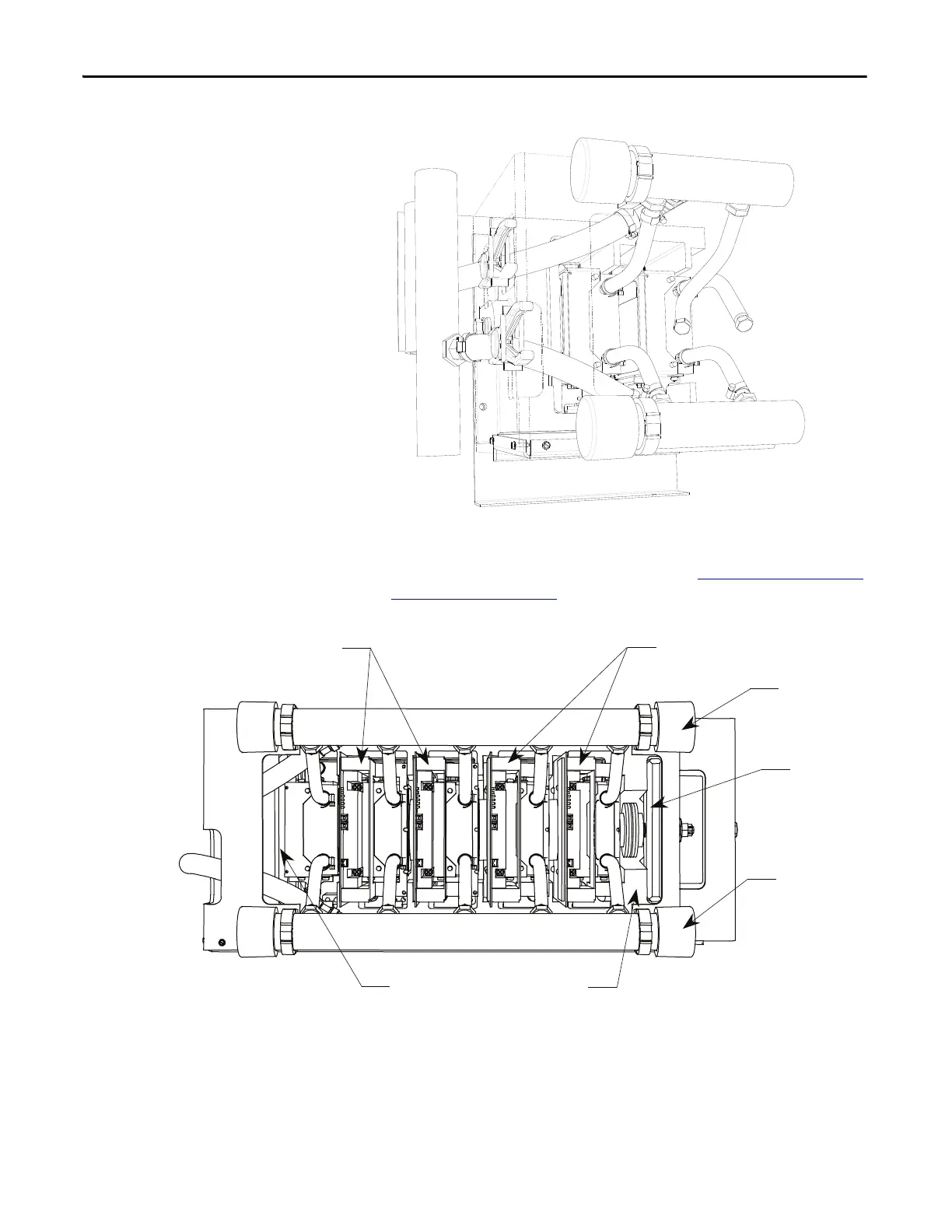
Figure 252 - Cooling System
Matched Set 2 SGCTs
Module Housing
Outlet Manifold
Clamp Base
Matched Set 2 SGCTs
Clamp Head
Inlet Manifold
 Loading...


