EasyManuals Logo

Rockwell Automation Allen-Bradley PowerFlex 750-21G Service Manual

Rockwell Automation Allen-Bradley PowerFlex 750-21G
352 pages
To Next Page IconTo Next Page
To Previous Page IconTo Previous Page
Page #219 background imageLoading...
Page #219 background image
Rockwell Automation Publication 750-TG100B-EN-P - June 2019 219
Power Bay Components Chapter 9
14. Place the fan and housing assembly on a support block that is on a solid
work surface, with only the fan in contact with a support block. The
support under the fan allows you to lift the metal housing off the fan unit
after the screws have been removed.
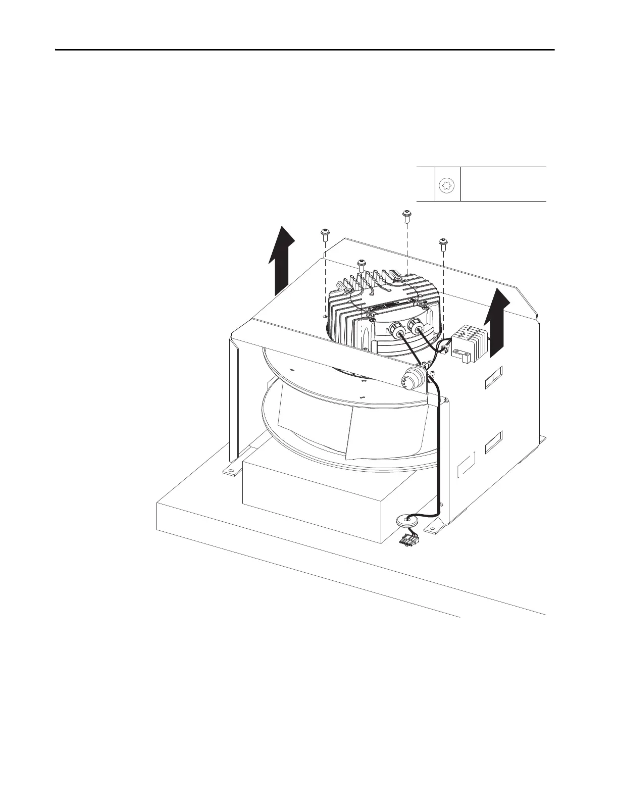
15. Remove the four M6 x 16 mm torx screws that secure the fan to the roof
assembly housing and lift the fan housing off the fan.
Install the IP54 Exhaust Fan
Install the IP54 exhaust fan on a power bay in the reverse order of removal.
15
M6 x 16 mm
T30
10 N•m (90 lb•in)

Table of Contents

Other manuals for Rockwell Automation Allen-Bradley PowerFlex 750-21G

Questions and Answers:

Question and Answer IconNeed help?

Do you have a question about the Rockwell Automation Allen-Bradley PowerFlex 750-21G and is the answer not in the manual?

Rockwell Automation Allen-Bradley PowerFlex 750-21G Specifications

General IconGeneral
BrandRockwell Automation
ModelAllen-Bradley PowerFlex 750-21G
CategoryDC Drives
LanguageEnglish

Related product manuals