4 Stratix 2000 Ethernet Unmanaged Switches
Rockwell Automation Publication 1783-PC002C-EN-P - May 2014
Connect the SFP Module
Insert a fiber optic cable with an LC connector into the SFP module (installed in the SFP fiber port). Optical SFP
communications modules are limited to Laser Class I only, and shall be UL certified.
Connect the Power Supply
Keep the following in mind when connecting the power supply to the switch:
• Use the supplied 3-pole, 5.08 mm (0.20 in.) or 5-pole 5.08 mm (0.20 in.) pitch terminal block to connect the
power wire.
• Use wires of 2.5…0.75 mm
(14…18 AWG).
• Grounding resistance must be <2.5
.
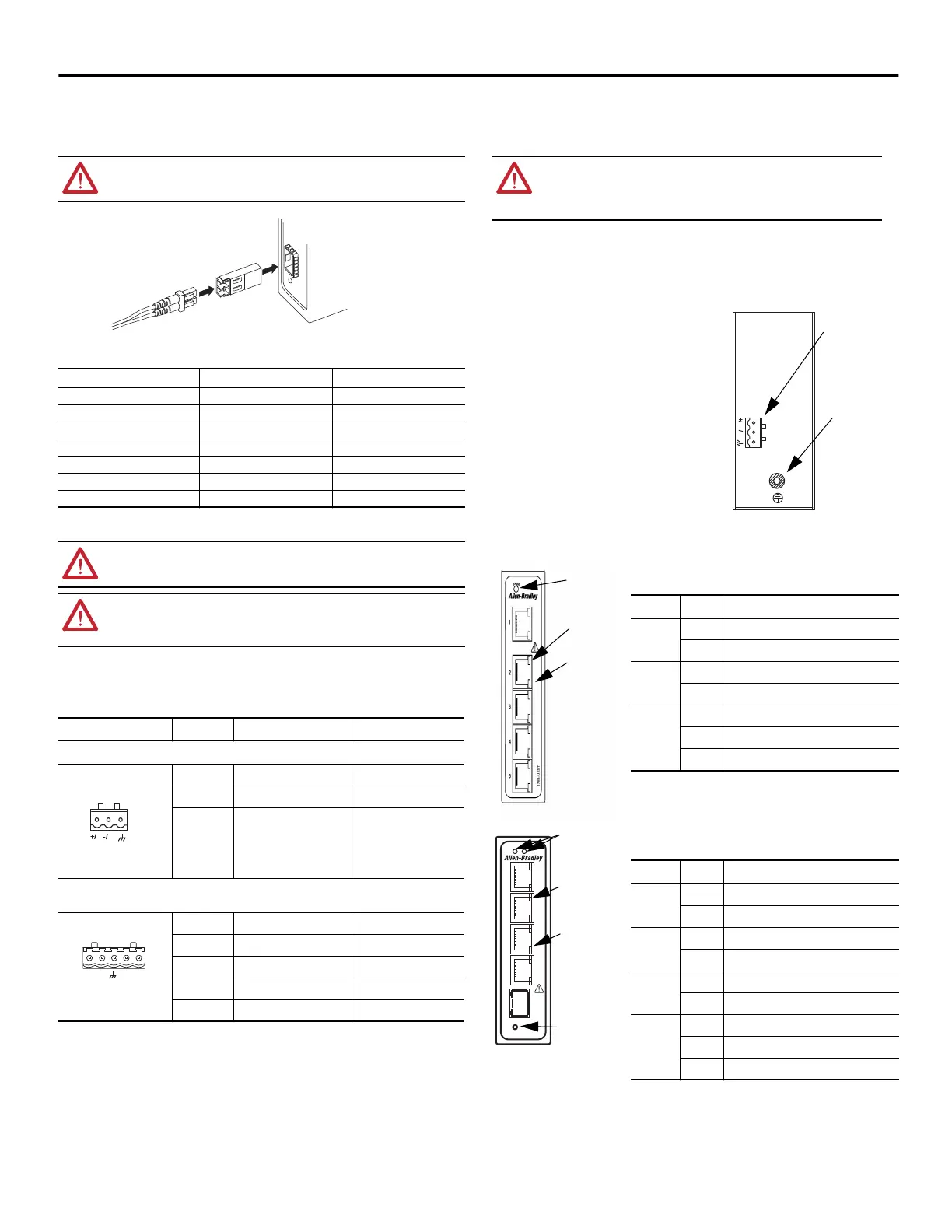
Follow this procedure to connect the power supply to the switch.
1. Disconnect the power terminal connector (on top of the switch) from the switch.
2. Insert the power wires into the power terminal connector.
For proper polarity of the power wiring, use the cable pinout above or the diagram on the switch label.
3. Tighten the power connector by using a screwdriver.
Torque must not exceed 0.5 N
m (4.42 lbin).
4. Plug the power connector back into the device.
Be sure the terminal is connected securely.
Ground the Switch
The switch has two grounding points, as follows:
• Functional Earth Ground (FE) in the power connector on the top
of the switch
• Protective Ground (PE) on the switch housing
Keep these points regarding grounding in mind:
• Grounding resistance for PE must be less than 2.5 .
• For proper grounding, use a suitable ring terminal for the
chassis PE ground screw, and minimum 2.5 mm
(14 AWG)
wire.
• Torque must not exceed 1.82 N
m (16.10 lbin).
Apply Power to the Switch
Once you apply power to the switch, if the ports are operating
normally, the following happens:
• The port status indicators flash for a short time.
• The PWR status indicator will be on continuously.
Status Indicators
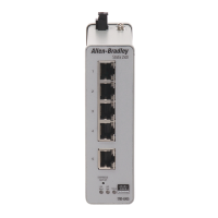
This illustration shows the 1783-US5T switch. These status indicators are the same as those found on the 1783-US8T
switch.
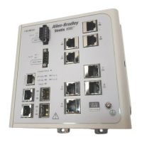
This illustration shows the 1783-US4T1F switch. These status indicators are the
same as those found on the remaining switches.
ATTENTION: Class 1 laser product. Laser radiation is present when the system is open and interlocks
bypassed. Only trained and qualified personnel should be allowed to install, replace, or service
this equipment.
SFP Module Parameters
Parameter Multimode Singlemode
Central wavelength (nm) 1310 1310
Transmission distance (km) 2 20
Applicable distance (km) 0…2 0…20
Luminous power, min (db) -19 -10
Luminous power, max (db) -10 -5
Receiving sensitivity (dBm) -31 -34
Overload luminous power -3 -3
WARNING: Before performing any of the following procedures, make sure power is removed from the
DC circuit or the area is nonhazardous before proceeding.
ATTENTION: To comply with the CE Low Voltage Directive (LVD), this equipment must be powered from a
source compliant with the safety extra low voltage (SELV) or protected extra low voltage (PELV). To comply
with UL restrictions, this equipment must be powered from a source compliant with Class 2 or Limited
Voltage/Current.
Diagram Pin For DC Wiring For AC Wiring
1783-US5T and 1783-US8T switches
1 PWR: + PWR: L
2 PWR: - PWR: N
3 Functional Ground (FE) Functional Ground (FE)
1783-US4T1F, 1783-US4T1H, 1783-US5TG, 1783-US6T2F, 1783-US6T2H, 1783-US6TG2CG, 1783-US7T1F,
1783-US7T1H, 1783-US14T2S, and 1783-US16T switches
1 PWR1:+ PWR1:L
2 PWR1:- PWR1:N
3 Functional Ground (FE) Functional Ground (FE)
4 PWR2: - PWR2: N
5 PWR2: + PWR2: L
32483
N
L
PWR
123
32315-M
PWR1
+/L -/N -/N +/L
PWR2
123
45
ATTENTION: This product is intended to be mounted to a well-grounded mounting surface, such a
metal panel. For safety and maximum noise immunity, the switch must be grounded by using the
Protective Ground (PE) grounding screw on the housing. Functional Earth ground (FE) is internally
connected to the PE ground. FE ground may be used to ground the DC power supply, for example. The
PE chassis ground must be connected to a reliable earth ground at all times.
Indicator Status Description
PWR ON Power is connected and operates normally
OFF Power is not connected or operates abnormally
SPEED
(Yellow)
On 100 M working state (for example, 100Base-TX)
Off 10 M working state (for example, 10Base-T)
LINK/ACT
(Green)
On Network is available
Blinking Network activity on the port
Off No network activity on the port
Indicator Status Description
PWR1 ON PWR1 is connected and operates normally
OFF PWR1is not connected or operates abnormally
PWR2 ON PWR2 is connected and operates normally
OFF PWR2 is not connected or operates abnormally
SPEED
(Yellow)
On 100 M working state (for example, 100Base-TX)
Off 10 M working state (for example, 10Base-T)
LINK/ACT
(Green)
On Network is available
Blinking Network activity on the port
Off No network activity on the port
N
L
PWR
Protective
Earth (PE) GND
PWR Connector
Speed Status
Indicator
LINK/ACT
Status Indicator
Power Status
Indicator
2
3
4
5
5
1
PWR1 PWR2
1783-US4T1F
Speed Status
Indicator
Copper (RJ45)
LINK/ACT
Status Indicator
PWR1 and PWR2
Status Indicator
SFP LINK/ACT
Status Indicator
 Loading...