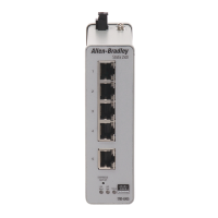
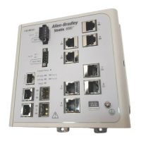
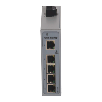
Stratix 2000 Ethernet Unmanaged Switches 3
Rockwell Automation Publication 1783-PC002C-EN-P - May 2014
Before You Begin
Observe these guidelines before installing the switch:
• For 10/100/1000 ports, the cable length from a switch to an attached device cannot exceed 100 m (328 ft).
• Clearance to front and rear panels must meet these conditions:
– Front-panel status indicators can be easily read.
– Access to ports is sufficient for unrestricted cabling.
– DC (or AC) power connectors are within reach of the connection to their power source.
• To prevent the switch from overheating, observe the following minimum clearances:
– Top and bottom: 50.80 mm (2 in.)
– Sides: 50.80 mm (2 in.)
– Front: 63.50 mm (2.50 in.)
• Temperature surrounding the unit must not exceed 60 °C (140 °F) for 783-US5T and 1783-US8T switches or
70 °C (158 °F) for all other switches.
Install the Switch on a DIN Rail
Follow these procedures to install the switch on a DIN rail.
1. Allow sufficient clearance between devices for ventilation and electrical isolation, based on the clearances listed in the
Before You Begin section.
2. Position the switch so that the top of the DIN rail mounting clip is slightly above the upper DIN rail edge.
3. With the bottom of the switch angled away from the panel, slide the switch downward until the mounting clip spring is
behind the top edge of the DIN rail.
4. Press the switch downward to compress the spring.
5. Press the bottom of the switch toward the panel until the clip locks into place over the bottom edge of the DIN rail.
Remove the Switch from a DIN Rail
1. Gently push the switch downward to compress the mounting clip spring.
2. Rotate the bottom of the switch away from the DIN rail until the bottom of the mounting clip is clear of the lower rail.
3. Lift the switch up until the mounting clip and springs clear the upper DIN rail.
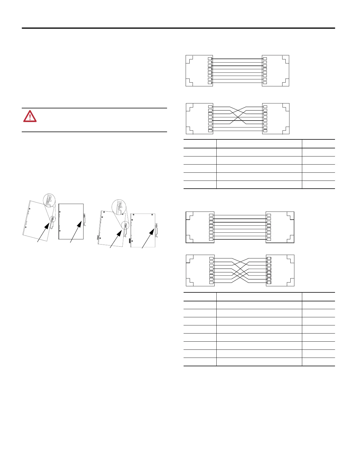
Wire the Switch
You can wire the switch for connection to the Ethernet network via copper or fiber ports.
For simplified cabling, the switch supports automatic medium-dependent interface crossover (auto-MDIX). With
auto-MDIX, the switch detects the required cable type for copper Ethernet connections and configures the interfaces
accordingly. You can use either crossover or straight-through cables for connections to the switch's 10/100/1000 Ethernet
ports, regardless of the type of device on the other end of the connection.
Use either straight-through or crossover style, twisted four-pair, Category 5e or better cables with RJ45 connectors to
connect to the switch's Ethernet ports.
Wiring Connections and Pins - 10/100 Copper Ports
Wiring Connections and Pins - 10/100/1000 Copper Ports
ATTENTION: When using DIN rail mounting, additional grounding is also accomplished through the
DIN rail to chassis ground. Use zinc-plated yellow-chromate steel DIN rail to assist in proper grounding.
The use of other DIN rail materials (for example, aluminum or plastic) that can corrode, oxidize, or are
poor conductors, can impede proper grounding. Secure DIN rail to mounting surface approximately
every 200 mm (7.8 in.).
32479
Switch DIN Rail
Mount (open)
Switch DIN Rail
Mount (closed)
1783-US4T1F, 1783-US4T1H, 1783-US5TG, 1783-US6T2F,
1783-US6T2H, 1783-US6TG2CG, 1783-US7T1F, 1783-US7T1H,
1783-US14T2S, and 1783-US16T switches
32313-M
Switch DIN Rail
Mount (open)
Switch DIN Rail
Mount (closed)
1783-US5T and 1783-US8T switches
Pins MDI-X Signal (+ and - represent the polarity of a wire) MDI Signal
1 RD+ TD+
2 RD- TD-
3 TD+ RD+
6 TD- RD-
4, 5, 7, 8 Not used Not used
Pins MDI-X Signal (+ and - represent the polarity of a wire) MDI Signal
1 TRD1+ TRD0+
2 TRD1 - TRD0-
3 TRD0+ TRD1+
4 TRD3+ TRD2+
5 TRD3- TRD2-
6 TRD0- TRD1-
7 TRD2+ TRD3+
8 TRD2- TRD3-
RJ45
RJ45
1 2 3 4 5 6 7 8
8 7 6 5 4 3 2 1
RJ45
RJ45
1 2 3 4 5 6 7 8
8 7 6 5 4 3 2 1
Straight-through Cable
Crossover Cable
RJ45
RJ45
1 2 3 4 5 6 7 8
8 7 6 5 4 3 2 1
RJ45
RJ45
1 2 3 4 5 6 7 8
8 7 6 5 4 3 2 1
Straight-through Cable
Crossover cable
 Loading...