3
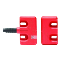
Minimum Distance Between Sensors
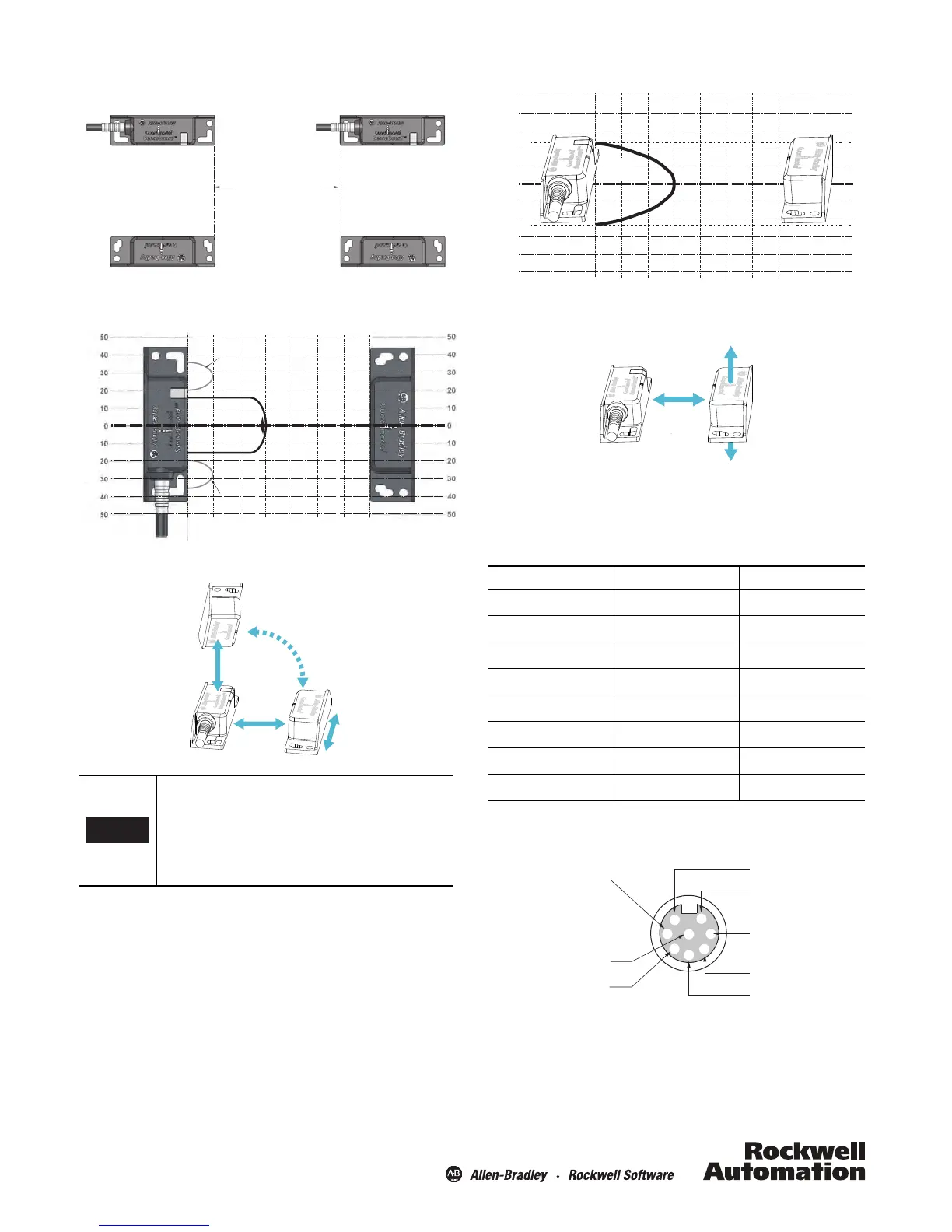
Misalignment Curve
Wiring Diagram
8-Pin Unit
Recommended mating cable, 2 m (6.5 ft)—889D-F8AB-2.
Replace the 2 with 5 (5 m) or 10 (10 m) for standard cable lengths.
Allow a minimum spacing of 9 mm (0.35 in.) if the
actuator and sensor faces approach laterally (from
the y-direction). This will prevent false triggering
due to the side lobe areas.
To ensure proper functioning of margin indication
(non-safety), z-direction approach is not
recommended for -N and -N9 models.
5
10
15
20
25
30
35
SIDE
LOBES
Sensing Distance* (mm)
0
SIDE
LOBES
ASSURED
SENSING
DIS TANC E
* when the actuator approaches the sensor in the x-direction or
from above (z-direction) and is misaligned in the y-direction
Sensor Actuator
Misalignment (mm)
Assured Make: 15 mm
Assured OFF: 35 mm
x
z
y
Sensor
Actuator
Actuator
Pin Number Wire Color Signal
1 White Aux. Outputs
2Brown+24V
3GreenNA
4 Yellow OSSD 2, +24V Input
5 Grey OSSD 1
6 Pink OSSD 2
7Blue0V
8 Red OSSD 1, +24V Input
5
10
15
20
25
30
35
Sensing Distance** (mm)
0
23
23
50
40
30
20
30
0
10
20
10
40
50
50
40
30
20
30
0
10
20
10
40
50
Misalignment (mm)
** when the actuator approaches the sensor in the
x-direction and is misaligned in the z-direction.
Sensor Actuator
ASSURED
SENSING
DISTANCE
Assured Make: 15 mm
Assured OFF: 35 mm
4
7
6
8
1
5
2
3
Brown
White
Blue
Pink
Grey
Green
Red
Yellow
 Loading...