8
-24
+14
-22
-20
-18
-16
-14
-12
-10
-8
-6
-4
-2
+0
+2
+4
+6
+8
+10
+12
d
B
r
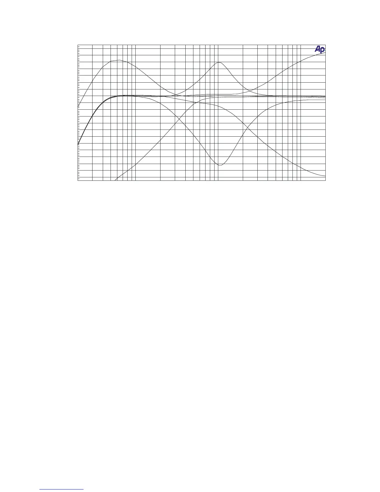
20 20k50 100 200 500 1k 2k 5k 10k
Hz
LOW MAX
LOW MIN
MID MAX
MID MIN
HIGH MAX
HIGH MIN
4) Input channel effects assign indication LED’s
These LED’s indicate which channel is routed trough one of the effects outputs. If the FX-1 and
FX-2 LED’s do not light up, no channel is routed via the effects. If the FX-1 LED of a channel
lights up green, that channel is routed via effects output 1. If the FX-1 LED of a channel lights
up red, one of the other channels is routed via FX-1 and no other channel can be routed via
FX-1 at that moment.
Same counts for the FX-2 LED that lights up. If the FX-1 LED is blinking red, the input channel
effects assign potentiometer (5) must be turned back to its center position because it was
initially placed in a fault position.
5) Input channel effects assign potentiometer
With this control, the input signal can be routed via effects output 1 or 2. When the knob is
placed in the center (12 o’clock) position, the signal goes straight to the main mix without
passing via one of the effects-outputs. When the knob is turned to the left, the signal will go via
the effects 1 output. When the knob is turned to the right, the signal will go via the effects 2
output. The proportion between the dry (no effect) and wet (100% effect) can be set with the
potentiometer.
6) Balance control
The balance between the amount of sound on the left and on the right is adjusted by using this
knob. When it is set to the center position, the gain is the same for both the left and the right
channel. When turned to the left, the right channel will decrease. When turned to the right, the
left signal will decrease.
7) Routing selector
With this selector the signal can be lead: to the left side of the crossfader (X), directly to the
output (MIX) or to the right side of the crossfader (Y).
8) PFL switches
With these switches you can select the different input sources that you will listen to with the
headphones.