EN
14
1 General safety precautions
Warning: incorrect installation may cause severe damageor injury. Read the instructions carefully before
installingtheproduct.
Thisinstallationmanualisintendedforqualiedpersonnelonly.
ROGERTECHNOLOGYcannotbeheldresponsibleforanydamageorinjuryduetoimproperuseoranyuseotherthe
intendedusageindicatedinthismanual.
Installation,electricalconnectionsandadjustmentsmustbeperformedbyqualiedpersonnel,inaccordancewith
bestpracticesandincompliancewithapplicableregulations.Beforeinstallingtheproduct,makesureitisinperfect
condition.
Disconnectthemainselectricalpowerbeforeperforminganywork.Onlyuseoriginalsparepartswhenrepairingor
replacingproducts.
Thepackagingmaterials(plastic,polystyrene,etc.)shouldnotbediscardedintheenvironmentorleftwithinreachof
children,astheyareapotentialsourceofdanger.
WARNING! Handle electronic parts and terminals with extreme care, as these parts are highly sensitive to static
electricity.
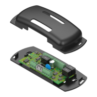
2 Product description
The B73/LTMisadevicethatcanbeconnectedtotheCTRLcontrolunit(FW P4.30versionorlater)oftheBIONIK
barriersandallowscontrollingtheRGBboomlightsandtheRGBheadlightsaswellassignallingthestatusof:fully
open,fullyclosedandcentralalarm.ItcanbeconnectedviathesuppliedwiringtotheLED LIGHT connector of the
CTRLcontrolunit,fromwhichittakespowerandcanbeconguredusingparameters10, 18, 70, 72, 74, 75, 79.
NOTE:usingtheRGBheadlightswillcausethewhiteashinglampunittolosefunctionality;therefore,ifnecessary,
installanexternalashinglampunitbyconnectingittotheLAMterminalofthecontrolunit.
3 Technical specications
B73/LTM
POWERSUPPLY
fromthewiringwhencombinedwiththeCTRLcontrolunit(jumperinINTposition)
fromterminalsV24_AUXandCOMwhencombinedwithothercontrolunits(futureuse,
jumpersinEXTposition)
RELAYCONTACT 3x30Vdc1A(pure,normallyclosedcontact,openstoissuetheerroralert)
ALR ERROR ALERT LED
ALR(controlunitinalarm)
TC(closed)
TO(open)
BOOMLIGHTOUTPUT RGBcontrol,24Vdc,500mAperline
HEADLIGHTOUTPUT
RGBcontrol,24Vdc,100mAperline
Alternatively:connectionof2externalrelaysformanagingmorepowerfultrafclights
thatneedtobesuppliedseparately(g.3)
4 Installation
NOTE: refer to gure 1 for connections.
1.Applythedouble-sidedadhesivetapetothebackofthecasingoftheB73/LTMboardorinsertB73/LTM into the
rails(ifpresent).
2.FastenthecasinginsidetheBOXoftheCTRLcontrolunit,ontheENCODER,LEDLIGHTandLOCKSterminalboard
side
3.ConnecttheB73/LTMboardtothecontrolunitusingthesuppliedwiringharness;replacetheharnessattachedto
theplasticcase(gure1-detailA)withtheoneprovidedbyconnectingthewirestotheterminalsSEM_24V,SEM_R,
SEM_G,SEM_B
4.ConnecttheRGBboomlighttotheterminalsLIGHTS_24V,LIGHTS_R,LIGHTS_G,LIGHTS_B
5.MakesuretheSEL_POWERjumperisintheINTposition
6.Switch on power to the CTRL control unit
5 Settings (g. 3-4)
The SEL_POWERjumpermustbeengagedintotheINTpositiontoreceivepowerdirectlyfromtheROGERTECHNOLOGY
controlunitviathesupplied4-wireharness.
Ifthecontrolunitisalreadyatitslimitforaccessorypower(photocells,etc.)andtheadditionoflightsexceedsthis
limit,itispossibletopowertheB73/EXPandRGBlightswithanexternalpowersupplytobeconnectedtoterminals
V24_AUXandCOM(seeg.4);inthiscasetheSEL_POWERjumpermustbesettoEXTposition.