DS-90/90A Feb. 2000
16
INFOMATION
SW2SW1
C33
C1
CN1 CN3
C35
AK4324
C32
CN2
C48
JK3
TORX178A
CS8412-CP
Roland
DS-90 DA BOARD
01897512
PWB G2927157
10pF
100Ω
0.1uF
0.1uF
0.1uF
0.1uF
0.1uF
0.1uF
0.1uF
0.1uF
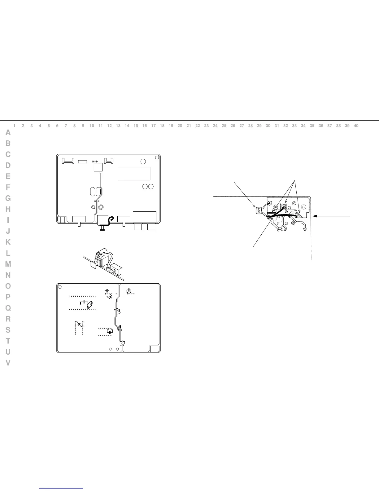
Cut the Gnd pattern (3 places).
Use a 0.1uF monolithic ceramic capacitor to
connect between Frame Gnd and A Gnd.
View from foil side
XLR Connector Backside
● The following changes were made to the early versions of the DS-90 BOARD.
Ground line is connected to the main body chassis.
0.1uF capactors are connected to the backside.
Use an electrical wire (AWG 24 or equivalent)
to connect to A Gnd (Signal Gnd).
View from components side
View from foil side
DA BOARD for DS-90 ANALOG SHEET for DS-90
(HEAD AMP BOARD BLOCK)

 Loading...