6
Apr. 2000SP-808EX
TEST MODE テストモード
テストモードテストモード
テストモード
Tools required
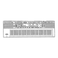
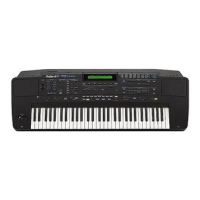
SP-808EX
Audio devices: CD player, DAT, audio signal generator,
amplifier, speaker, headphones
Foot pedal: DP-2 or equivalent
Oscilloscope
Zip drive
*Additional devices to test SP808-OP1
CD player or the like having "COAXIAL" and "OPTICAL"
output capability
DAT or the like having "COAXIAL" and "OPTICAL" input
capability
Zip drive (SCSI TYPE)
Cables (SCSI/COAXIAL/OPTICAL)
♦
Identifying the version number
While in the test mode, the top of the screen displays the
CPU software version and the system software version in the
format shown below:
1.00 1.000
Left: CPU version; right: system version
♦
Entering the test mode
1. While holding STATUS (track D) and EFFECT (track D)
buttons under RECORDER/MIXER, turn on POWER
switch. See Note: in step 4 below.
2. When "CHECK SP808-OP1 .." appears at the center of
the screen, release the buttons.
3. Test options will be displayed. Among the test options
shown below, options 1. LCD to 4. Switch are displayed
on the initial screen.
4. If the option board, SP808-OP1 is installed, "OP-1"
appears on the upper right-side of the screen.
Note: When the Zip drive is to be used during test,
connect it before turning on the SP-808EX. Set
Termination to "ON" and SCSI ID to "6".
5. As mentioned before, the top of the LCD screen display
shows the CPU software version (at the left) and the
system software version (at the right).
LCD display Test option
1. LCD LCD contrast 1
2. LCD Contrast LCD contrast 2
3. LED LED check
4. Switch Switch check
5. Encoder VALUE dial check
6. Fader Fader potentiometer check
7. Pot Rotary potentiometer check
8. Beam Beam check
9. Foot SW Foot switch check
10. MIDI MIDI check
11. Zip Zip drive check
12. SCSI SCSI check (only when option
board, SP808-OP1 is installed)
13. Analog I/O Analog inputs/outputs check
14. Digital I/O Digital inputs/outputs check
(only when option board, SP808-OP1 is
installed)
15. Initialize System data initialization
To select a test option, use cursor buttons [ ] and [ ] to
move cursor [>] on the leftmost of the screen to the test option.
Then, press [ENTER/YES] button. After the test, the screen
exits to the menu screen.
♦
Test description
1. LCD check
1.1 When this option is selected, the LCD displays "Push
[>] KEY" at the center of the screen.
1.2 Press [>] button blinking in green. The all dots on the
LCD will be turned on.
Press [>] button again. The all dots will be turned off.
使用機材
使用機材使用機材
使用機材
SP-808EX
オーディオ機器
( CD PLAYER , DAT , OSCILLATOR ,
AMPLIFIER , SPEAKER , HEADPHONE )
フットペダル(
DP-2
等)
オシロスコープ
ZIP DRIVE
*
SP808-OP1
のテストをする場合は、更に以下の機器が必
要になります。
" COAXIAL "
及び
" OPTICAL "
出力端子付
CD PLAYER
等
" COAXIAL "
及び
" OPTICAL "
入力端子付
DAT
等
Zip Drive ( ZIP-EXT-2S )
ケーブル
( SCSI / COAXIAL / OPTICAL )
◎バージョンナンバーの確認方法。
◎バージョンナンバーの確認方法。◎バージョンナンバーの確認方法。
◎バージョンナンバーの確認方法。
SP-808EX
のシステム・ソフトウェアのバージョンは、
テスト・モード中に確認する事が出来ます。
テスト・モードに入ると
LCD
画面上部に、
CPU
ソフト
ウェアのバージョンとシステム・ソフトウェアのバージョン
が以下の様に常時表示されます。
1.00 1.000
(表示の左側が
CPU
ソフトウェアのバージョン、右側が
SYSTEM
ソフトウェアのバージョンです。)
◎テストモードへの入りかた。
◎テストモードへの入りかた。◎テストモードへの入りかた。
◎テストモードへの入りかた。
1.
RECORDER / MIX
部の
[ STATUS ( D
トラック
) ]
ボタン
と
[ EFFECT ( D
トラック
) ]
ボタンの2つのボタンを同
時に押しながら、
SP-808EX
の電源スイッチを入れます。
2.
" CHECK SP808-OP1 .. "
と
LCD
画面の中央に表示が出
たら、2つのボタンから手を離します。
3.テストモードに入ると、各テスト項目が以下の様に
LCD
画面に表示されます。(初期画面は、
"
1.
LCD
〜4.
Switch "
までが表示されます。)
4.オプションボード(
SP808-OP1
)が装着されている場合
は、
LCD
画面右上に、
" OP-1 "
と表示されます。
また、
Zip
ドライブを検査に使用する場合は、
Termination " ON "
、
SCSI ID " 6 "
に設定し、
SP-808EX
の電源を入れる前に、接続しておきます。
5.テストモードの
LCD
画面上部、左側に
CPU
バージョ
ン、右側に
SYSTEM
バージョンが表示されます。
LCD
画面表示 <チェック項目>
1.
LCD LCD
コントラストチェック①
2.
LCD Contrast LCD
コントラストチェック②
3.
LED LED
チェック
4.
Switch
スイッチチェック
5.
Encoder
バリューダイヤルチェック
6.
Fader
フェーダーボリュームチェック
7.
Pot
ロータリーボリュームチェック
8.
Beam
ビームチェック
9.
Foot SW
フットスイッチチェック
10
.
MIDI MIDI
チェック
11
.
Zip Zip Drive
チェック
12
.
SCSI SCSI
チェック「オプションボード
( SP808-OP1 )
取付け時のみ」
13
.
Analog I/O
アナログ入出力チェック
14
.
Digital I/O
デジタル入出力チェック「オプション
ボード
( SP808-OP1 )
取付け時のみ」
15
.
Initialize
システムデータの初期設定をします。
チェック項目を選ぶ場合は、上下のカーソル
[
▲▼
]
ボタン
を押してチェックしたい項目に
LCD
画面内左端のカーソル
"
>
"
を合わせた後、
[ ENTER / YES ]
ボタンを押します。各
項目をチェックし、終了すると、メニュー画面に戻ります。
◎検査項目の説明
◎検査項目の説明◎検査項目の説明
◎検査項目の説明
1.
LCD
チェック
①.チェックの画面に入ると、画面中央に
" Push
[>]
KEY "
と表示されます。
②.
"
次に、
[
>
]
再生ボタン(緑の
LED
が点滅している)
を押すと
LCD
画面の全てのドットが
ON
になり、も
う一度、
[
>
]
再生ボタンを押すと
LCD
画面の全ての
ドットが
OFF
になります。
1.3 If necessary, press the button to repeat turning on/off
of the dots.
To exit the test, press RECORD button (
•
)
blinking in red.
2. LCD contrast check
2.1 When this option is selected, the LCD displays
"CONTRAST = 5" on the bottom of the screen.
2.2 Turn the VALUE/TIME dial and verify changes in
contrast.
When the dial has successfully changed the value
"CONTRAST = **" from 0 to 15, the center area of the
screen displays "LCD OK !!".
To exit the test, press RECORD button (
•
)
3. LED check
3.1 When this option is selected, the LCD displays "Push
[<<] [>>] KEY" and all LEDs are turned on.
3.2 Press MEAS [>>] button. All LEDs are turned off
except for "DISK".
3.3 Press MEAS [>>] button repeatedly. The remaining
LEDs are turned on one by one, from the upper left
one.
Note: The STATUS LED first lights in red and then in
green at the second press of the MEAS button.
3.4 When all the LEDs are turned on and kept on, the
center area of the screen displays "LED OK !".
To exit the test, press RECORD button (
•
).
4. Switch check
4.1 When this option is selected, the right-hand area of
the screen displays "067" and "****" just below the
figures.
4.2 Press and hold a button. The "****" is replaced with
the button name or the button symbol.
The graphic image on the screen shows the approx.
location of the button being held down. If all LEDs are
blinking, you are pressing two buttons.
4.3 Turn on the remaining buttons one by one. When all
the buttons have been pressed, the upper-right area
of the screen displays "* SW OK !!*".
To exit the test, press RECORD button (
•
)
5. Encoder check
5.1 When this option is selected, the LCD displays graphic
which moves left and right as the VALUE dial is turned
counter-clockwise and clockwise, and associated
"Value: **" reading just below it.
5.2 Verify that reading "Value: **" changes from 0 to 100
as the VALUE dial is turned.
When the reading covers this range, the upper-left
area of the screen displays "OK !!".
To exit the test, press RECORD button (
•
).
6. Fader check
6.1 When this option is selected, the left-hand area of the
screen displays graphics representing 6 faders.
6.2 These graphic faders move from bottom to the top as
the corresponding fader is slid up and down.
6.3 When the fader successfully moves its full travel
range, "OK" is displayed above and below the
corresponding graphic fader on the screen.
6.4 Repeat the steps 6.2 and 6.3 for the remaining faders.
When all the faders pass the test, "OK !!" is displayed
at the center of the screen.
To exit the test, press RECORD button (
•
).
7. Rotary potentiometer check
7.1 When this option is selected, the LCD displays
graphics representing 3 REALTIME EFFECT
potentiometers.
7.2 Turn a potentiometer from MIN to MAX and verify that
the corresponding graphic potentiometer also turns.
③.以降、ボタンを押す毎に
ON / OFF
を繰り返します。
この状態で
[
●
]
録音ボタン(赤い
LED
点滅している)を押
すと、この項目のテストを終了出来ます。
2.
LCD Contrast
チェック
①.チェックの画面に入ると、
LCD
画面下段に
"
CONTRAST = 5 "
と表示されます。
②.次に、バリューダイヤルを回すとコントラストが変化
します。
" CONTRAST =** "
の数値を0〜15と変化させる
と、
LCD
画面中央に
" LCD OK !! "
と表示されます。
この状態で
[
●
]
録音ボタンを押すと、このテスト項目を終
了する事が出来ます。
3.
LED
チェック
①.チェックの画面に入ると、
" Push [<<] [>>] KEY "
と表
示され、全ての
LED
が点灯します。
②.次に、
[
>>
] MEAS
ボタンを押すと、
" DISK "
の
LED
のみ点灯します。
③.以降ボタンを押す度に、左上の
LED
から順に一つず
つ点灯していきます。
(
" STATUS "
の
LED
は2色
LED
なので、初め赤の
LED
が点灯し、再度ボタンを押すと次に緑の
LED
が
点灯します。)
④.全ての
LED
を順に点灯させると、全ての
LED
が点灯
し、
LCD
画面中央に
" LED OK ! "
と表示されます。
この状態で
[
●
]
録音ボタンを押すと、このテスト項目を終
了する事が出来ます。
4.
Switch
チェック
①.チェックの画面に入ると、
LCD
画面右側に
" 067 "
と
表示され、その下段に
" ***** "
と表示されます。
②.次に、いずれかのボタンを押すと、押されたボタンの
名前または記号が、押されている間のみ
" ***** "
の部
分に表示されます。
また、ボタンのおおよその配置が、ボタンを押す度に
グラフィックで
LCD
画面に表示されますが、2個以
上同時にボタンが押されると、全
LED
が点滅して注
意を促します。
③.全てのボタンが押されると、
LCD
画面右上に
" * SW
OK !! * "
と表示されます。
この状態で
[
●
]
録音ボタンを押すと、このテスト項目を終
了する事が出来ます。
5.
Encoder
チェック
①.チェック画面に入ると、
VALUE
ダイヤル(エンコー
ダー)の動作に連動して、左右に動くグラフィック表
示と、その下に
" Value : ** "
と表示されます。
②.次に、
VALUE
ダイヤルを左右に回すと、
" Value : ** "
の**の部分の数値が0〜100と変化します。
数値が0〜100まで正常に変化した場合は、
LCD
画
面右上に
" OK !! "
と表示されます。
この状態で
[
●
]
録音ボタンを押すと、このテスト項目を終
了する事が出来ます。
6.
Feder
チェック
①.チェック画面に入ると、
LCD
画面左側にフェーダー6
本の状態がグラフィックで表示されます。
②.各フェーダーを上下すると、それに対応した
LCD
画
面のグラフィック表示のフェーダーが上下します。
③.下端から上端までフェーダーが正常に動作をした場合
は、
LCD
画面のグラフィックのフェーダーの上下にそ
れぞれ
" OK "
の表示が出ます。
④.全てのフェーダーに
" OK "
の表示が出た場合、画面中
央に
" OK !! "
の表示されます。
この状態で
[
●
]
録音ボタンを押すと、このテスト項目を終
了する事が出来ます。
7.
Pot
チェック
①.チェック画面に入ると、パネル
REALTIME EFFECT
部のロータリーボリューム3個の状態が
LCD
画面に
グラフィックで表示されます。
②.各ボリュームを回転させると、それに対応した
LCD
画面のグラフィック表示のボリュームも回転します。
 Loading...