Jan,
1990
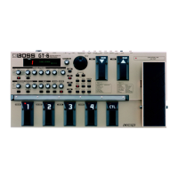
GP-16
GP-16 SUB
BOARD/GP-16 SUB
ASSY 17049322
NOTE:
Relacement
should
be done on
a PCB
assy
bassis
and not
on
individual
parts
which are
not
available
from
the
factory.
Replacement
SUB board
is
furnished
with
wirings
(green,
and yellow)
and
1C
socket
(14
pin).
This
board is
mounted
on some
early
products
only
(prior to
SN
ZA96249 but
excluding
prior
to
SN Z**2749.
When
servicing
products
bearing
above-
mentioned
SN and
without
SUB PCB, order
it
as
an additional
one.
For
mounting
,
details refer
to
SUB Board
Mounting
Considerations
on
page 21. Also
see
Change
Information
(p. 22)
for the
reason
why
this
board
is
necessary.
BOARD
GP-16
SUB BOARD ii,
life
<h <D
7
7
•V-,
IC V
X
v
Y
(
14pin)
o
t LX,
7 1
£
h
GP-
1 6
<D
y
')
r;i
ZA96249
Mfre-To
ttz,
y'J
T)V
•
Z
**
2749
GP-16
Kit, GP-16 SUB BOARD
±1
(Z**2749
Mtu)
K$>
XitZh GP-16
^U^X^tzb,
^
GP-16
SUB BOARD
LX
GP-16
SUB
BOARDS
IX
<0
tfitXTZb'o
"GP-16 SUB
BOARD
WC\
#±(Dy±^*”(P.
21)
22)i0M
LX
\T$^o
/
21
CONSIDERATIONS
ON
MOUNTING
SUB BOARD
/SUB
BOARD
NOTE:
Remove a
47
pF
capacitor across
IC13 pins 4
and 8 on the
main
board, if soldered. See Fig.
1.
GP-16
bearing
Prior
to
SN Z**2749)
is not furnished
with SUB
board. Added
this PCB as
follow:
1.
Desolder IC15 (TC74HC132P) on the
main
board.
(Fig.
2)
2. insert
the
board into holes where IC1
5
was and
solder. (Fig. 3: Next page)
NOTE: (When the board has been on the existing
main board (SN ZA82750-ZA96249),
remove the IC socket from the new board
and reuse the existing one.) (Fig. 4: Next
page).
(Referring to Fig. 5:
Next
page)
&
:
IC13<7)4#
\±yb
47pF
(DZ2
HZtlX^tzb,
(Fig.
1
#HS)
GP-16 <7)vU
74/
•
f-'yzi-
Z
**
2749
7
7^
GP-16 SUB BOARD
£
flX
I'Z-XX^X,
9
wtr
$
v>
0
1.
±|E
<Dir')T)V
•
j-'SJ*—
(Z**2749
M0
<7)^7
IC15
K
TC74HC132P
X^h<DX,
(Fig.
2
0M)
GP-16 SUB BOARD
&
IC15
(OiXM
.
(-H
(Fig.
3
#M
:
y±
:
y'J
T)l
•
t>A-
ZA82750-ZA96249<7)GP-16
it, GP-
1 6
SUB
BOARD
ZtlX^'Zt
COX',
GP-16
SUB BOARD
IC V
X v
Y
(U^'s)*it'?LX,
WLK%&ZtiX\t'Z>
VX?
(Fig.
4
0m
:
Tifio
3
5 <D^mKx>\,*Xit,
Fig.
5
#03
:
o
3.
Bend
IC10 pin 31 and
solder it to
the solder pool
but 3. IC10
<7)31#
fcf
X7)fe£-
ffiPf,
$|<7)-^EEIy§f
£
9
(3#EH
not to the orginal
conductor pattern
connecting
to
ftlti"
h
0
pin 31 terminal.
y±
:
&
<h<7)31#t?
!
4.
Solder the
yellow
wiring
to
the solder pool next to
pin 31.
4. IC10 <7)31#
tf
9
K3tfe<Dilft#£#ffl
5. Solder the green
wiring
to
pin 4 of IC13.
5. IC13
<7)4#tf
£
0

 Loading...