EasyManua.ls Logo

Roland JC-40 User Manual

Roland JC-40
31 pages
To Next Page IconTo Next Page
Page #1 background imageLoading...
Page #1 background image
SERVICE NOTES
Issued by RJA
Copyright © 2015 Roland Corporation
All rights reserved. No part of this publication may be reproduced in any form without the written permission
of Roland Corporation.
CC-KWS17057004E0
JC-40Nov. 2015
Table of Contents
Cautionary Notes ..............................................................2
Specifications .....................................................................3
Location of Controls .........................................................4
Exploded View (Cabinet).................................................5
Plain View (Cabinet).........................................................6
Plain View (Cabinet) Parts List .......................................7
Exploded View (Chassis) .................................................8
Exploded View (Chassis) Parts List................................9
Plain View (Chassis) .......................................................10
Important Notes When Binding Wiring......................11
Wiring Diagram/Block Diagram..................................12
Parts List...........................................................................14
Verifying the Version......................................................16
Test Mode.........................................................................16
Circuit Board (Main, Jack, Volume, PS, Inlet Board) .18
Circuit Diagram (Main Board: 1/4)..............................20
Circuit Diagram (Main Board: 2/4)..............................22
Circuit Diagram (Main Board: 3/4)..............................24
Circuit Diagram (Main Board: 4/4)..............................26
Circuit Diagram (Jack Board) ........................................28
Circuit Diagram (Volume Board) .................................30
Circuit Diagram (PS Board) ...........................................31
Circuit Diagram (Inlet Board) .......................................31
Question and Answer IconNeed help?

Do you have a question about the Roland JC-40 and is the answer not in the manual?

Roland JC-40 Specifications

General IconGeneral
Amplifier class-
RMS rated power40 W
Number of speakers2
Audio output channels2.0 channels
Audio (L/R) in1
Headphone connectivity6.3 mm
Connectivity technologyWired
Suitable forAcoustic-electric guitar
Product colorBlack
Power source typeAC
ManualYes
Weight and Dimensions IconWeight and Dimensions
Depth251 mm
Width592 mm
Height436 mm
Weight15800 g

Summary

Cautionary Notes

No User Data

User data is not saved, so backup during servicing is not required.

Part Replacement Guidelines

Procedures for replacing components, especially near heat-generating circuits.

Parts List Information

Reasons why certain parts are not supplied as service parts.

Circuit Diagram Notations

Explanation of 'NIU' and 'UnPop' for non-mounted components.

Product Specifications

Rated Power and Input Levels

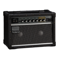
Details on power output and input signal specifications.

Speaker and Control Specifications

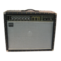
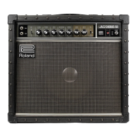
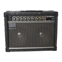
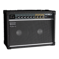
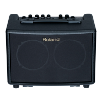
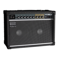
Information on speaker size and front panel controls.

Connector Types

Lists all input, output, and effect loop connectors.

Power, Dimensions, and Weight

Electrical power, physical size, and weight of the unit.

Accessories and Options

Lists included accessories and optional items.

Control and Connector Layout

Front Panel Control Identification

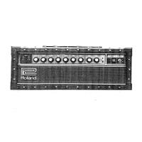
Identifies all front panel knobs, switches, and indicators.

Rear Panel Connections and Switches

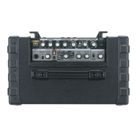
Identifies rear panel jacks, switches, and AC inlet.

Cabinet Exploded View

Cabinet Assembly Overview

Diagram of the main cabinet structure.

Cabinet Hardware and Fittings

Identification of handles, corners, and feet.

Speaker and Back Board Components

Exploded view of speakers and back board.

Chassis Exploded View

Main Chassis Structure

Diagram of the primary chassis assembly.

Circuit Boards and Major Components

Identifies circuit boards and key components like power amp.

Front and Rear Panel Components

Details of jacks, knobs, and spacers on the chassis.

Chassis Component Diagrams

Chassis Front View Details

Specific component labels for Chassis View 8.

Chassis Rear View Details

Specific component labels for Chassis View 9.

Wiring Binding Precautions

Component Clearance for Wiring

Keep wiring away from resistors and diodes.

Transformer Wiring Best Practices

Route primary wiring under transformer to avoid screw tips.

LED Wiring Safety

Ensure LED wiring is clear of the fuse.

System Wiring and Block Diagrams

Main Board Signal Flow Overview

Block diagram of signal paths on the main board.

Wiring Harness Identification

List and description of internal wiring harnesses.

Component Parts List

Casing, Chassis, and Knob Parts

Lists parts for cabinet, chassis, and knobs.

Switch, Jack, and Speaker Parts

Lists parts for switches, jacks, and speakers.

PWB, IC, Diode, and Potentiometer Parts

Lists circuit board assemblies, ICs, diodes, and potentiometers.

Fuse and Fuse Holder Parts

Lists fuse and fuse holder components.

Additional Parts List Information

Wiring, Cables, and Transformer Parts

Lists wiring harnesses, cables, and the power transformer.

Screws, Fasteners, and Miscellaneous

Lists screws, nuts, washers, and general hardware.

Standard Accessories Included

Lists items supplied with the product.

Test Mode Operations

Version Verification Procedure

Method to check firmware version using LED patterns.

DSP and Switch Function Tests

Tests for DSP chip and front panel switches.

Volume Control and Knob Tests

Verifies volume and other knob operations with LED feedback.

Signal Input/Output Testing

Input/Output Signal Level Verification

Checks signal levels against specifications for various I/O paths.

Speaker Output Performance Test

Verifies speaker output level and waveform distortion.

Residual Noise Measurement

Measures noise floor at output jacks and speaker terminals.

Circuit Board Layout Diagrams

Main Board Layout

Visual layout of the main circuit board.

Jack, Volume, PS, and Inlet Board Layouts

Layouts for auxiliary circuit boards.

Main Board Circuit Diagram (Part 1)

Volume and ADVR Circuitry

Circuit details for volume controls and ADVRs.

Microcontroller and EEPROM Interface

Connections to the CPU and EEPROM.

Main Board Circuit Diagram (Part 2)

Power Supply and Regulator Circuits

Power input and voltage regulation stages.

Audio Amplifier Stages

Circuit diagrams for power amplifiers.

Main Board Circuit Diagram (Part 3)

Input Signal and EQ Paths

Circuitry for input signals and equalization.

DAC Output Stages

Digital-to-analog converter output paths.

Main Board Circuit Diagram (Part 4)

Op-Amp Filter Configurations

Diagrams of operational amplifier filter circuits.

Speaker Mute and Monitoring Circuits

Circuits related to speaker muting and signal monitoring.

Jack Board Circuit Diagram

Return Jack Signal Processing

Circuitry for the RETURN jacks.

Analog Jack Signal Paths

Signal routing for other analog jacks.

Volume Board Circuit Diagram

Potentiometer and Switch Wiring

Connections for volume controls and switches.

Interface to Main Board

Wiring between volume board and main board.

Power Supply (PS) Board Circuit Diagram

PS Board Power Circuit

Diagram of the power supply board.

Inlet Board Circuit Diagram

Inlet Board AC Connections

Wiring for the AC inlet.

Related product manuals