右左右左
右 左右 左
12
11-2. When test ends, press [ENTER].
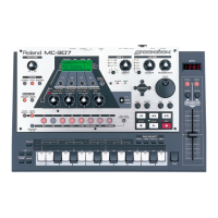
MC-505 uses the FLASH MEMORY. So the program can be update the
program by transferring the data from the upgrading disk (SMF format),
through MIDI.
NOTICE : Before executing this software upgrade(including "Factory
Preset"), save user data referring to the section "Saving and
Loading user data", if necessary. If not , the user data will be
erased.
SS Required Items
•MC-505 Version Up Disk Set (PNo. 17048669)
(The Version up disk contains the MC-505 program converted into SMF
data.
Obtain the latest version from the service center.)
•Sequencer ÅiAnything that will playback SMF will do.
•MIDI cable
SS Update procedure
1. Connect MIDI OUT of the Sequencer with MIDI IN of the MC-505.
2.Turn the power on while holding down [TEMPO/MIXER], [PTN SET]
and [PATCH] button.
Display shows as follows.
3. Press the [ENTER] button, then MC-505 checks the ROM-ID number.
And display shows as follows.
Check to see that the display shows as described above and then
playback the SMF data.
When the update procedure is in normal operation, [PATCH] LED will
blink.
The file names are as follows.
_000001.mid
_000002.mid
|
_000016.mid.
(For cases where program data volume is small, the file count is less
11−2.テストが終了したら、[ENTER]を押します。
MC−505は、プログラムROMにフラッシュメモリーが使用されて
いますので外部シーケンサーよりMIDIによるプログラムのアップデ
ートが可能です。手順は下記のとおりです。
注意:このアップデート(含むファクトリープリセット)を実行する前
に、もし必要なら、ユーザーデータをバックアップして下さい。
実行するとユーザーデータが消去されます。
◇ 用意するもの
・MC−505 Ver.Up Disk(部品番号 17048669)
( Ver.Up DiskにはMC−505のプログラムをSMFにコ
ンバートしたものが入っています。サービスセンターから最新のもの
を取り寄せて下さい。)
・SMFプレーヤー(シーケンサー)
(SMFデータが再生できれば何でもよい。XP−80等)
・MIDIケーブル
◇ バージョンアップ作業
1.MIDIケーブルを外部シーケンサーの MIDIOUTから MC-505の
MIDIINにつなぎます。
2.MC-505の [TEMPO/MIXER]、[PTNSET]、[PATCH]を押しながら
電源を入れると、次の画面が表示されます。
3.[ENTER]を押すと ROM-IDをチェックして下図のような表示になり
ます。
上の表示を確認してから、外部シーケンサーをプレイします。正常にバ
ージョンアップされていると [PATCH]の LEDが点滅します。
ファイルの名前は、000001.mid〜 000016.midでプログラムサイズに
よっては16個より少ない場合もあります。プレイ中に各ファイルのチ
ェックサムが "One="の後に、累計のチェックサムが "Al="の後に表示
されます。
全てのファイルをプレイし終わったら最終の累計チェックサムを確認し
ます。
than 16.)
While playing, a check sum appears on the display.
One=**** : Check sum of the each file.
Al=**** : Total.
After all the files have been played, compare the original checksum
(described on disk label) with the current checksum for discrepancy.
4. Perform the Factory Preset Data loading.
(See page 7(FACTORY PRESET) for more details.)
NOTICE : As for MC-505, this procedure must be carried out after
executing the update procedure.If not, some strange problem
may occur later.
The update procedure is now complete.
1. Adjusting DBeam controller
When you replace MAIN ESCT ASSY, DBeam controller adjustment is
necessary.
1-1. Remove the bottom cover.
1-2. Connect the test probe of the oscilloscope to the Tap
Point of the MAIN BOARD.
TP 1: + TP 2: -(GND)
1-3. Adjust the voltage output from TP 1 to 0V by using
VR1.
NOTE : When you adjust the voltage, be sure to keep MC-
505 in a horizontal position, and keep any object and
strong light (fluorescent lamp etc.) away from around
the photoreceiver.
Please don't observe the voltage in a state of the
photoreceiver side down.
2. Group wires
The wirings that connect MAIN ESCT BOARD ASSY and PANEL
BOARD are tied.
This action is necessary to keep wirings from contacting with Power
Supply Unit.
Once you cut the tie, please take this action again for safety.
4.ファクトリープリセットを実行します。 (詳しくは7頁(ファクト
リープリセットデータのロード)を参照のこと。)
注意:MC−505に関しては、アップデート終了後、この手順を必ず
実行し て下さい。もししなければ、使っていくうちに動作がおか
しくなる可能性が あります。
以上でアップデートは完了です。
1.Dbeamコントローラーの調整
メインボードを交換した場合は、 DBeamコントローラーの調整が必要です。
1−1. ボトムカバーを開けます。
1−2. オシロスコープのプローブをメインボードに接続しま
す。
TP1:+、TP2:− 接地側(GND)です。
1−3. メインボードの VR1を回して、 TP1から出力される
電圧を、0Vになるようにしてください。
注意: 電圧を観測するときは、本体を水平に保ち、Dbea
m コントローラーの受光部にものを近づけたり、蛍光
燈などの強い光があたらないようにして作業を行って
ください。
受光側を作業机に向けて伏せたまま、電圧を観測しな
いようにしてください。
2.ワイヤリングの結束
メインボードとパネルボードをつなぐワイヤリングは、工場出荷時には結
束されています。
これは、電源ユニットとワイヤリングが接触しないために必要な措置です。
修理のために結束を外した場合は、修理完了時に必ず元どおりに結束し直
してください。
Result of Test
/テストの結果
One of the dot is not lit
/
点灯しないドットがある
Contrast of the LCD is not changed
Contrast of the LCD is pale, even if
adjust its contrast maximum level.
Contrast of the LCD is dark , even if
adjust its contrast minimum level
/コントラストが変化しない
最大にしても薄い、最小にしても濃い
Check
/チェック項目
Replace the LCD unit.
/LCD を交換してください
Check R262
Is PWM waveform input to the QFP side of the R262?
/R262をチェック
QFP側の端子に、PWM波形が入力されていますか
Check IC31
Check the condition of connection of resistors and capacitors, and its input / output voltage.
/IC31をチェック
抵抗やコンデンサの接続状態、入出力電圧
Make hot and cool TH1, if the bounds of the contrast change
is large, there is a possibility that the component is broken
/TH1を温めたり冷やしたりしてみる
コントラストの変化が大きい場合、破損の可能性があります
Check DA8
Is there short in the circuit ?
If the above check points are normal, replace the LCD unit.
Test Mode complete.
/DA8をチェック
破損により短絡していないか
上記に異常が見られない場合、LCDを交換
Troubleshooting for the LCD Test/LCDテストトラブルシューティング

 Loading...