17
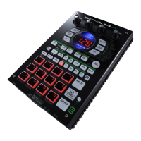
SP-404
2. Input/Output Jack Check (LINE IN,
LINE OUT, PHONES)
“Lin” appears in the display.
Audio signals input to LINE IN are output by the SP-404 to LINE OUT and
PHONES.
Check the signals from LINE OUT and PHONES.
If there is no problem with the signals, disconnect the cable from LINE IN L/R;
the e procedure automatically advances to “3. Mic Check.”
3. Mic Check
“MiC” appears in the display.
Audio signals input to MIC are output by the SP-404 to LINE OUT and
PHONES.
Check the signals frOM LINE OUT and PHONES.
1. MIC LEVEL
Set this to the maximum level.
2. External Mic
Input sounds to the mic connected to the MIC jack and check the signals from
LINE OUT (or PHONES).
If there is no problem with the signals, disconnect the cable from the MIC jack.
3. Internal Mic
Input sounds to the internal mic and check the signals from LINE OUT (or
PHONES).
4. MIC LEVEL
If there is no problem with the signals, rotate the MIC LEVEL knob and check
to confirm that the level changes properly..
If there is no problem with the knob, press the [MIC] button; the procedure
automatically advances to “4. Switch/LED Check.”
4. Switch/LED Check
1. Display Illumination
Check visually and note whether the illumination lighting the area around the
display (the red LEDs) light, both above and below.
2. Seven-Segment LEDs
Check visually and note whether the seven-segment LED display lights in the
sequence.
3. Switch/LED
Press the buttons with lit LEDs in sequence.
There is a total of 45 switches, with the LEDs lighting in the following
sequence.
* All of the LEDs light when the buttons up to [MIC] have been pressed.
4. PEAK
Confirm that the PEAK LED is lit, then proceed to press the following button
in sequence given (the following buttons do not have LEDs).
[TAP TEMPO] -> [CANCEL] -> [REMAIN] -> [SUB PAD]
Buttons without LEDs are indicated in the display as shown below.
“tAP” : [TAP TEMPO]
“CAn” : [CANCEL]
“rEN” : [REMAIN]
“SUb” : [SUB PAD]
5. If all of the switches operate properly, the procedure automatically
advances to “5. Volume Check.”
5. Volume Check
1. CTRL 1
Rotate the [CTRL 1] knob from the minimum value (left) to the maximum
value (right).
The value indicated in the seven-segment display (left column) changes in
accordance with the movement of the knob; the dot lights if the test is passed.
If an incorrect value is detected, the procedure returns to the beginning of “5.
Volume Check.”
2. CTRL 2
Rotate the [CTRL 2] knob from the minimum value (left) to the maximum
value (right).
The value indicated in the seven-segment display (center column) changes in
accordance with the movement of the knob; the dot lights if the test is passed.
If an incorrect value is detected, the procedure returns to the beginning of “5.
Volume Check.”
3. CTRL 3
Rotate the [CTRL 3] knob from the minimum value (left) to the maximum
value (right).
The value indicated in the seven-segment display (right column) changes in
accordance with the movement of the knob; the dot lights if the test is passed.
If an incorrect value is detected, the procedure returns to the beginning of “5.
Volume Check.”
If the check finishes without error, the procedure automatically proceeds to “6.
Demo Play Check.”
6. Demo Play Check
Demo Play cannot be performed without a test memory card inserted in the
memory card slot.
The demo song plays automatically.
Confirm that the demo song is played correctly.
Rotate the [VOLUME] knob and confirm that the volume level changes
properly.
After confirming the above, press [MIC]; the procedure automatically proceeds
to “7. Residual Noise Check.”
7. Residual Noise Check
Set [VOLUME] to maximum and check the residual noise.
If there is no problem, turn off the power to the SP-404.
8. Backup Load
Following Test mode, all user data is erased.
After completing Test mode, reload the previously saved user data to the SP-
404.
Test mode is finished once the user data is completely loaded.
 Loading...