165
ADJUSTMENT
OSCILLATOR
0.
1/0.5
He
M-165
DUAL-TRACE
OSCILLOSCOPE
This
adjustment
needs ultra
low frequency
(0.1-0.5Hz)
square
waveforms of
TTL level
(OV and 5V),
which
may
not
be available from
ordinary test
oscillators
and
dual-trace osilloscope.
Consequently, some
possible
al-
ternatives
are illustrated.
M-132
(«
# #
#
-'
I
1
,n
w
#
9
1 I i
-
h’
Q
I •
o
Roland
NOTE:
Refer to
ALTERNATIVE-3
for single-beam
scope.
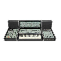
MAIN
BOARD
©TM6
©TM1
GTM3
0TM5
PORTAMENTO
TIME
The
same procedures are
applicable
to
both
CH-1 and
CH-2. First,
adjust CH-1, then
CH-2 looking
CH-1
waveforms
as standard.
More
to the point, synchronize
all phases
of
CH-1 and
CH-2 overlapped on the
screen.
•
ONE SECOND
Patch
Instruments
and set M-132 and M-165
as
shown.
M-132 MIXER-2
SIG IN
3
to
0
(OV).
Set test oscillator
to
0.5Hz.
Adjust TM-1
(TM-3) on MAIN BOARD
so that the
times required
for horizontal line
on the scope
to
reach from
OV to
-i-5V
and
from
-i-5V
to OV are one
second each, (see below)
•
FIVE SECOND
Set oscillator
to 0.1
Hz.
Set M-132
MIXER-2
SIG IN 3
to
10
(10V).
Adjust TM-6
(TM-5) on
MAIN BOARD
so
that the time required
for horizontal line
to reach -t5V
or
to
return
to OV is
five
seconds.
TM-1
(TM-3) and
TM-6
(TM-5) interact. Repeat the adjustments,
maybe
3-5
times.
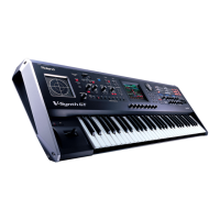
M-150
(140)
'v
»
ALTERNATIVE-1
TEST
OSCILLATOR
If the
MC-4 is available,
use
its CV
output.
CVDATA;
0
=
OV STEP TIME: 2000
=
0.1
Hz
60=5V
400=
0.5Hz
120
=
10V Other paremeters: Initial
setting
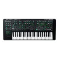
ALTERNATIVE-2
TEST
OSCILLATOR
This setup
makes
SYSTEM-1
OOM
150 and 132
a test
oscillator.
1.
(Do
not
connect Patch
(J)
yet)
Adjust
M-132 MIXER-1
out for
5Vp-p.
2.
(scope
time
base 0.2s/cm)
Adjust
M-150 FREQ
(approx,
at
9)
for 0.5Hz.
|«-
1 sec
1 sec
3.
Add
Patch (T).
(scope time
base 0.5s/cm)
4.
Adjust
M-132 -OUT (approx,
at
3)
for
0.1
Hz.
h
5sec
-4'
5sec
H
SYSTEM-100M
165
MAR. 25
,
1983
M-150 (140)
000
00
OSCILLATOR
or
MC-4
See
NOTE below
SINGLE-BEAM
OSCILLOSCOPE
M-165
B
'~.
Wo
M-132
5]
T
I
»
m
m
m
T
'
*r,nr
—
1
>
-p
-OUT
1
1 Roland
|
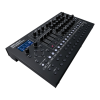
ALTERNATIVE-3
USING
SINGLE-BEAM
SCOPE
1.
Do
not
connect H IN
yet.
2. Set scope V
IN to GND
and RANGE
to
1 V/cm.
3. Position
scope
spot as shown
below.
4. Connect
scope H IN
to
M-165
PORTA-2
CV OUT.
5. Set scope V IN
to DC.
NOTE:
When
using the
oscillator
or the
MC-4,
refer to the
left for
test
signal setup.
__
1
y-
1
.
I
.
. .
....
..._t
-L
|_
!
1,
1
;
J
PORTAMENTO-1
•
ONE
SECOND
1. Disconnect
Patch
(J)
(dotted
line).
2. Set M-132
MIXER-2 SIG IN 3 knob to
0
(OV).
3. Set
M-165 changeover switches;
PORTAMENTO-1
to ON
and
PORTAMENTO-2 to
OFF
4.
Turn TM-1 CW until display stops
(foldover) for a
period
at
points
(J)and
(^,
then
reverse TM-1
slightly
just enough
for smooth beam
running with-
out reducing
displayed V
amplitude (5Vp-p).
•
FIVE SECOND
1. Connect Patch(3)(dotted
line).
2. Set
M-132 MIXER-2
SIG IN
3 to
10
(10V).
3. Similarly, adjust TM-6 for smooth sweep
running without reducing vertical
amplitude.
4. TM-1
and TM-6
will interact. Repeat these adjustments until
no
improve-
ment
is noted.
rrr
t
—
&
1
:
i
j
:
I
'
'
!
i i
I
^
.u
PORTAMENTO-2
•
ONE SECOND
1. Disconnect Patch(T)(dotted
line).
2. Set M-165 PORTAMENTO-2
to ON.
3.
Set M-132
MIXER-2
SIG IN
3 to 0.
4.
Adjust TM-3
so that Lissajous
is single line as possible.
•
FIVE SECOND
1. Connect
Patch(T)(dotted line).
2.
Set M-132
MIXER-2
SIG
IN 3 to 10.
3. Similarly,
adjust
TM-5
for
single
line
trace.
4. TM-3 and
TM-5 will interact. Repeat
these adjustments until
no improve-
ment is noted.
4
 Loading...