EasyManua.ls Logo

ROLL-ROAD EMMA - Safety Checklist

Default Icon
42 pages
Print Icon
To Next Page IconTo Next Page
To Previous Page IconTo Previous Page
Loading...
28
8. Wire connection diagram
8. Standard wire connection sequence
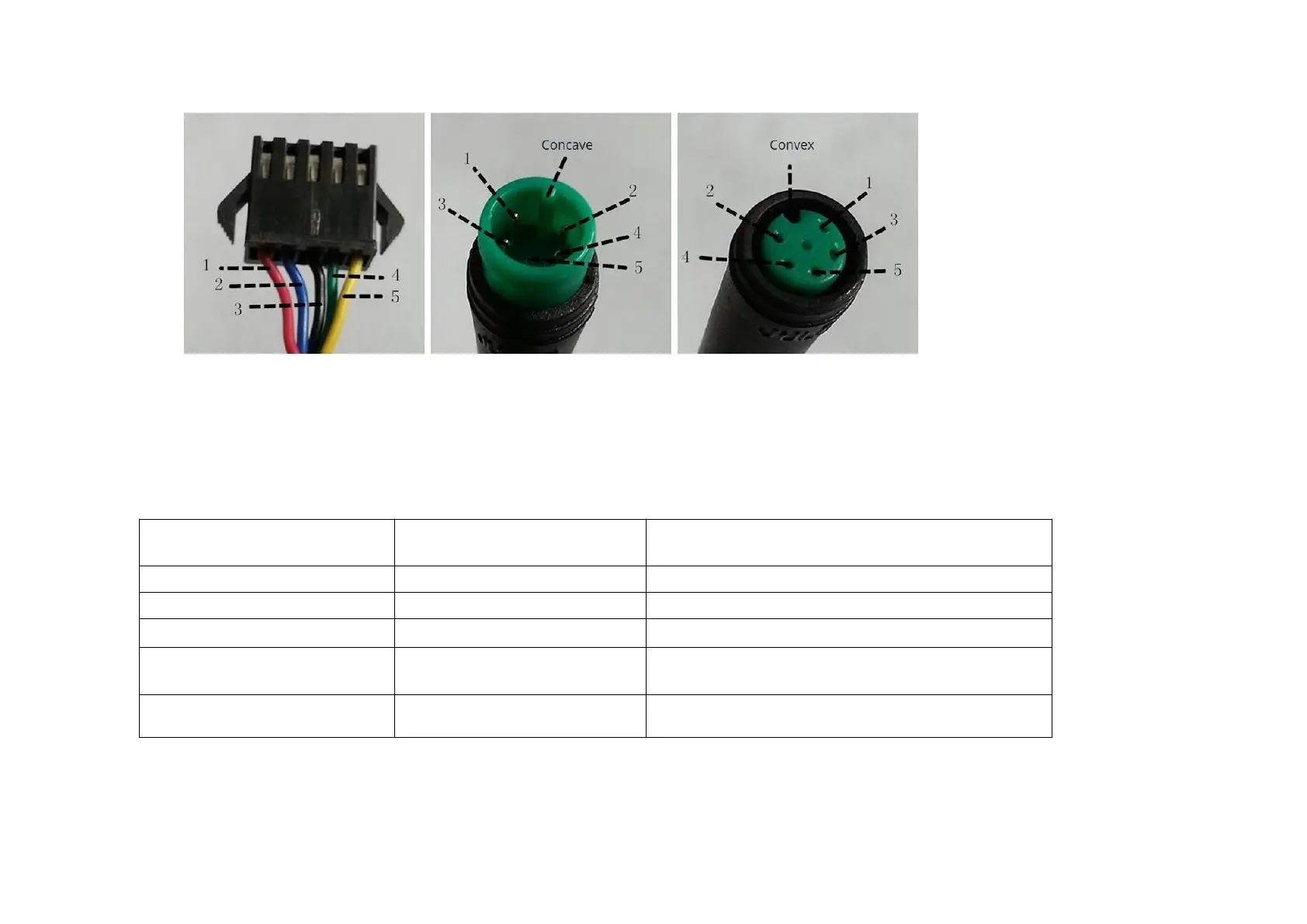
Controller connector Display connector (Female terminal) Display connector (Male terminal)Figure 8-1 Wire Connection Diagram
Table 8-1 Standard connector wire sequence table
Standard Wire Sequence
Standard wire color
Function
1
Red (VCC)
Display power wire
2
Blue (Kp)
Controller power wire
3
Black (GND)
Display ground wire
4
Green (RX)
Display data reception wire
5
Yellow (TX)
Display data transmit wire
1.
Some models are equipped with waterproof connectors and the color inside wires can not be seen.

Related product manuals