EasyManua.ls Logo

ROLLAND ROLLTWIN - Page 10

ROLLAND ROLLTWIN
61 pages
Print Icon
To Next Page IconTo Next Page
To Previous Page IconTo Previous Page
Loading...
Original instruction : French NT0002 V h 03/2012
10
Bed control: There are several types of floor controls, in each, several functions can be
managed from the electrical control box in the cabin in addition to the tractor control valve that is
always available. Here in this table are the various available combinations: Wiring diagram for
tractor troubleshooting (independent hydraulics).
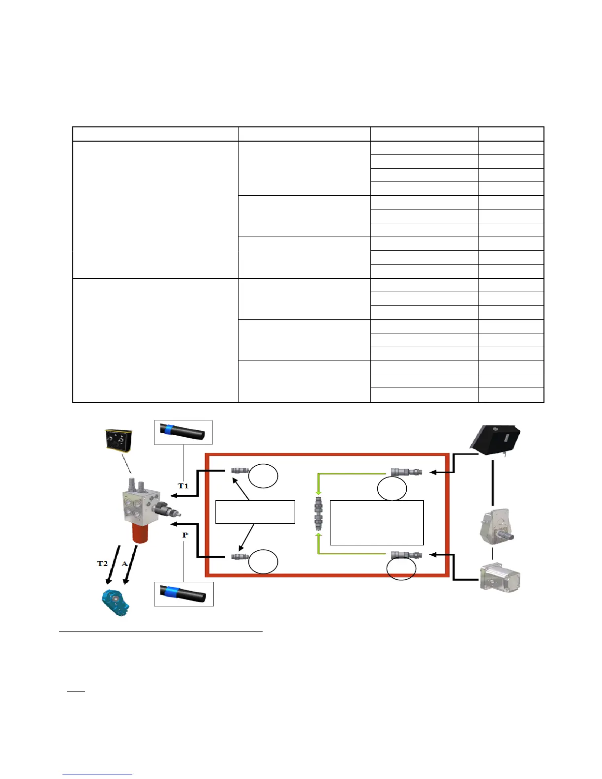
Procedure for carrying out a tractor repair: 1-
Disconnect push-pull 1 + 2 and push-pull 3 + 4
1- Connect push-pull 2 + 4 together with connection kit K1
2- Connect push-pull 1 pressure side of tractor distributor
3- Connecte push-pull 3 to reflux side of tractor distributor
Floor control
Function
Command
n° feed
1) Directly from the tractor:
operates through
hoses connected to the
tractor
1) Basic:
Bed only
manual control
110
no display
111
with display
112
with display + DPA
113
2) 2 functions :
Bed + slurry door
no display
121
with display
122
with display + DPA
123
3) 3 functions :
Bed + slurry door +
hood
no display
131
with display
132
with display + DPA
133
2) Pump:
The pump is operated
mechanically from the PTO and
the gearbox located upstream
(during maintenance or repair,
the hoses can be connected to
the tractor as in the diagram
here below)
1) Basic:
Bed only
no display
211
with display
212
with display + DPA
213
2) 2 functions :
Bed + slurry door
no display
221
with display
222
with display + DPA
223
3) 3 functions :
Bed + slurry door + hood
no display
231
with display
232
with display + DPA
233
to tractor
Do not forget to
plug in this
connector set K1
N.B : To reverse the direction, P and T1 must be inverted, i.e. the push-pull 1 and 3 on the tractor.
1
3
2
4