Original instruction : French NT0002 V –h – 03/2012
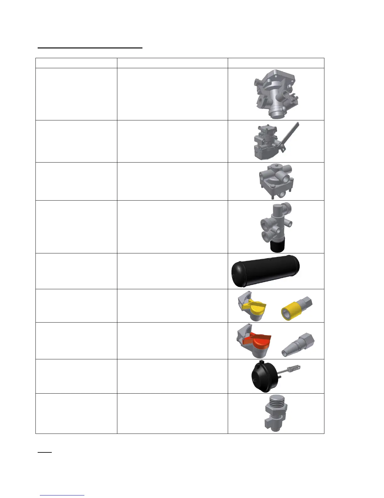
Emergency relay valve
(VRU)
Ensuring the service brake and
the automatic braking of the
trailer in case of coupling
breakage or pressure drop in the
supply line
Static corrector
(optional)
Adjusts the brake pressure, that
is the brake force, depending on
the load condition of the vehicle.
Allows the control circuit to
control the permanent circuit.
Allows the release of the service
brake of the trailer after initiation
of automatic brake caused by the
disconnection of the hoses.
Compressed air tank. The purge
allows the moisture in the circuit
to be evacuated.
Coupling control
controler
(yellow)
Permits the braking between
tractor and trailer
Ensuring the continuous supply
between the tractor and trailer.
Ensuring the service brake
system with its front part and the
parking brake with its rear part for
the dual spring cylinder.
Used to control the pressure in
the system
N.B : The brake can also be mixed (hybrid pneumatic/ hydraulic fitting)
(mounting for 40 kmh prohibited)