Rolls-Royce
&
Bentle
y
-------
Air
Conditioning
System
Manual
Back-seat
the
high
pressure
service valve and
forward-seat
the
low
pressure
service valve.
Connect
the
centre
union
of
the
manifold
gauge
set to the refrigerant container
and
open
the
valve
of
the container. Break
the
joint
of
the
manifold
centre
hose
and
purge
the air for a
few
seconds, then re-tighten.
Attach
a
spring
balance
to
the refrigerant
container and record the weight. Open the vacuum
of
'
the
manifold
gauge
set.
Start
the engine and switch
on
both
blower
motors.
If
the
refrigerant
does
not
fl.ow
into the
system,
even
with
the
compressor
in
operation,
place the container in a bucket
of
warm
water not
exceeding
113
° F. Do not apply a
flame
, or localised
heat. This could cause an explosion.
Do
not allow
the
reading
on
the
compound
gauge
to
exc
eed
50
lb
./
sq.in. This
can
be
controlled by regulating
the
vacuum
valve
of
the
manifold
gauge set.
When
7 lb.
of
refrigerant
has
been
drawn
into
the
system,
switch
off
the
ignition
and
close the
vacuum
valve
of
the manifold gauge set.
Close the valve
of
the
Freon
12
container
and
disconnect the centre hose. Back-seat
both
service
valves
on
the compressor.
Disconnect
and
remove
the
manifold gauge set
and
refit
the
protective
covers
on
the service valves. Check the system for
leaks,
adopting
the
following
procedure.
TO
CHECK
FOR
LEAKS
Leak
detection should
be
carried
out
at
full
operating
pressure
and
under
static
conditions,
using
the
Detector
Lamp
RH.527
(see under
pressure
tests
for
appropriate
figures).
In
order
to obtain the correct pressure, it
may
be
necessary
to re-charge the system.
·
'a:..
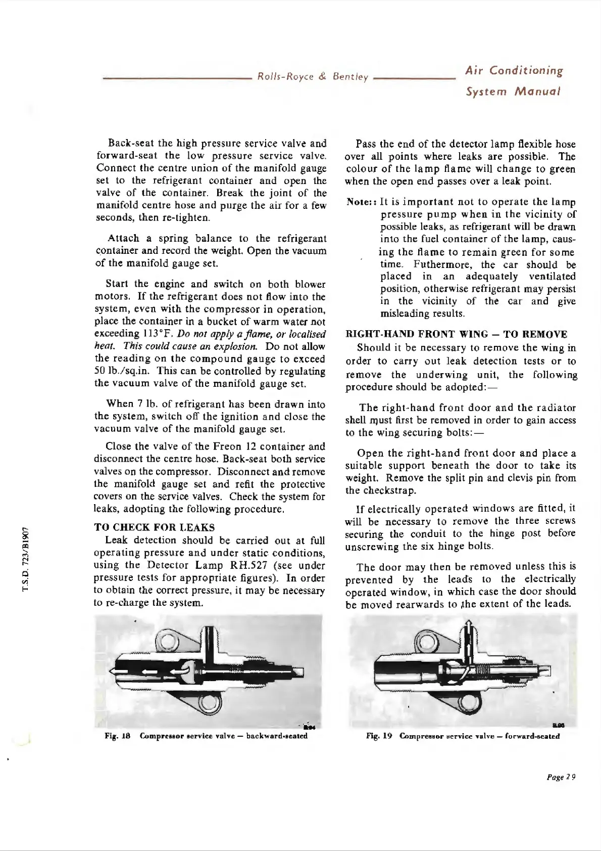
Fig.
18
f..omprcssor
service
valve
-
backward-seated
Pass the
end
of
the
detector
lamp
flexible hose
over all
points
where leaks
are
possible. The
colour
of
the
lamp
flame
wilJ
change
to
green
when the
open
end
passes over a leak point.
Note::
It is
important
not
to
operate
the
lamp
pressure
pump
when
in
the
v
icinity
of
possible leaks, as refrigerant will
be
drawn
into
the
fuel
container
of
the Lamp, caus-
ing
the
flame
to
remain
green
for
some
time.
Futhermore
, the
car
should
be
placed
in
an
adequately
ventilated
position, otherwise refrigerant may persist
in
the
vicinity
of
the
car
and
give
misleading results.
RIGHT-HAND
FRONT
WING - TO REMOVE
Should
it
be
ne
ces
sary
to
remove
the
wing
in
order
to
carry
out
leak
detecti
on tests
or
to
remove
the
underwing
unit,
the
following
procedure
should
be
adopted:-
The
right-hand
front
door
and
the
radiator
shell
fl1USt
first be removed in order
to
gain access
to the wing
securing
bolts
: -
Open
the
right-hand
front
do
or
and
pla
ce a
suitable
support
beneath
the
door
to
take its
weight. Remove the split pin
and
clevis
pin
from
the checkstrap.
If
electrically
operated
windows
are
fitted, it
will be
ne
cess
arv
to
remove
the three screws
securing the cor{duit to
th
e hinge post before
unscrewing the six
hinge
bolts.
The
door
may
then
be
removed
unless
this
is
prevented
by
the
leads
to
the electrically
o
perated
window
, in which case the
do
or
should
be
moved
rearw
a
rd
s to
,th
e
extent
of
the leads.
ua
Fig,
19
Compree~or ~
ervice
Yah
·e -
forw1ud-seated
Page
'l9