--------
-
----
Rolls-Royce &
Bentley-------
Cl
Air
Conditioning
System
Manual
Section
Ct
DESCRIPTION
The
vapour
compression system used on Rolls-
Royce and Bentley cars
is
designed
to
reduce the
temperature and humidity
in
the saloon when
surrounding air temperature and humidity are high.
To achieve greater efficiency, Jablite
roof
insulation,
'Sundym' (tinted) glass and an exhaust
heat
shield are
used to minimise heat penetration into the car
interior.
Circulation
of
the refrigerant, Freon I 2 (
DI-
CHLORODIFLUOROMETHA NE),
is
maintained
by a compressor, driven through the medium
of
an
electromagnetic clutch and
Vee
belts (see Fig.
2).
The
purpose
of
the compressor is two-fold; to
raise the pressure
and
temperature
of
the refrigerant
vapour and also
to
pump
the refrigerant through
the system. The high pressure, high temperature
vapour
is
delivered by the compressor to the con-
denser which
is
mounted
in
front
of
the radiator
matrix. Ambient air passes across the condenser
tubes by the forward motion
of
the
car
and engine
fan
action.
This air, which
is
of
a lower temperature than the
refrigerant vapour circulating through the condenser,
creates a heat transfer between these two media.
Condensation
of
the vapour occurs, creating a liquid
refrigerant (see Fig. 3).
The high pressure and high temperature liquid now
passes to the receiver, which
is
a storage tank located
just below the condenser, through the filter drier
and
sight glass to the expansion valve located in the
evaporator assembly in the boot (see Fig. 4).
This automatic thermal expansion valve
is
the
dividing point, separating the high pressure and low
pressure sides
of
the system. It automatically meters
the high pressure, high temperature liquid refrigerant
through a small orifice into the low pressure area
of
the
evaporator
coil. The low pressure
is
created by
the pull
of
the low pressure (suction) side
of
the
compressor.
At this point, as the liquid pressure
is
immediately
decreased, the temperature will correspondingly de-
crease. Heat laden air from the
car
interior
is
passed
over the evaporator coil
fins
and tu
bes
(through
which the now cold refrigerant liquid
is
circulating),
by
twin blower motors, via the return air
c1ucts.
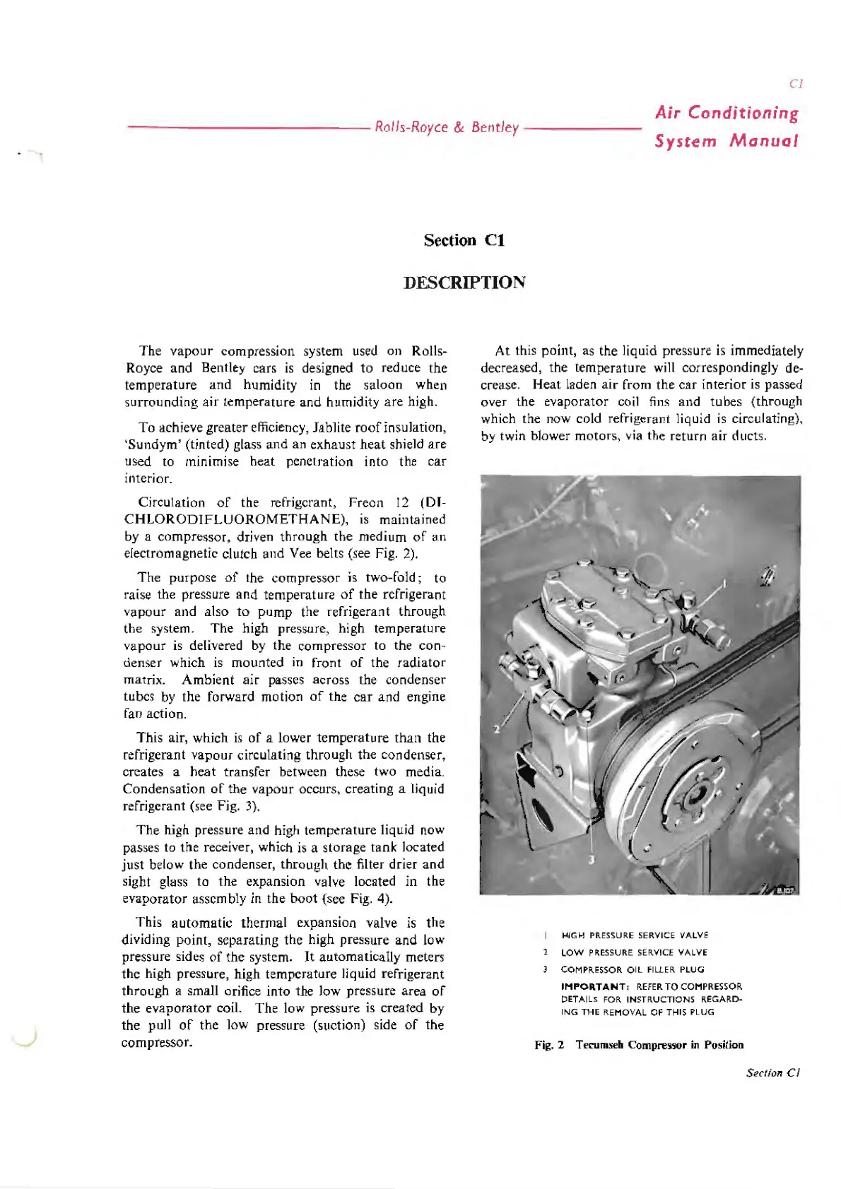
HIGH
PRESSURE
SERVICE VALVE
1
LOW
PRESSURE
SERVICE VALVE
3 COMPRESSOR
OIL
FILLER PLUG
IMPORTANT,
REFER
TO
COMPRESSOR
DETAILS
FOR
INSTRUCTIONS REGARD-
ING
THE REMOVAL OF THIS PLUG
Fig. 2
Tecumseh
Compn~or
in
Position
Section
Cl