C\I
-
-----------
- - Ro/is-Royce &
Bentley-------
Air
Conditioning
System
Manual
THE BY-PASS SOLENOID VALVE
Model-Danfoss
EVJD-6 (Stamped
FXM
or
FXMW
on
the valve body).
The
solenoid valve
is
mounted
midway along
the
right-hand
valance and
is
connected
in
the by-pass
line between the
compressor
intake
pipe
and
the
condcmer.
Operation
of
the valve
is
governed by a
thermostatic
switch controlled by a phial
in
the
evaporator
matrix.
The
purpose
of
this valve
is
to
control
the
degree
of
cooling, preventing icing
of
the
evaporator,
and
to
maintain
a
minimum
pressure
of
2 lb/sq. in. on the
low pressure side
of
the system.
To
maintain this
pressure, high pressure
vapour
from the
condenser
is
passed
through
the valve
and
reintroduced
to
the
suction side
of
the compressor. This also prevents
too
heavy a pressure
drop
in the
compressor
crankcase
,
which
could
cause priming
of
the oil.
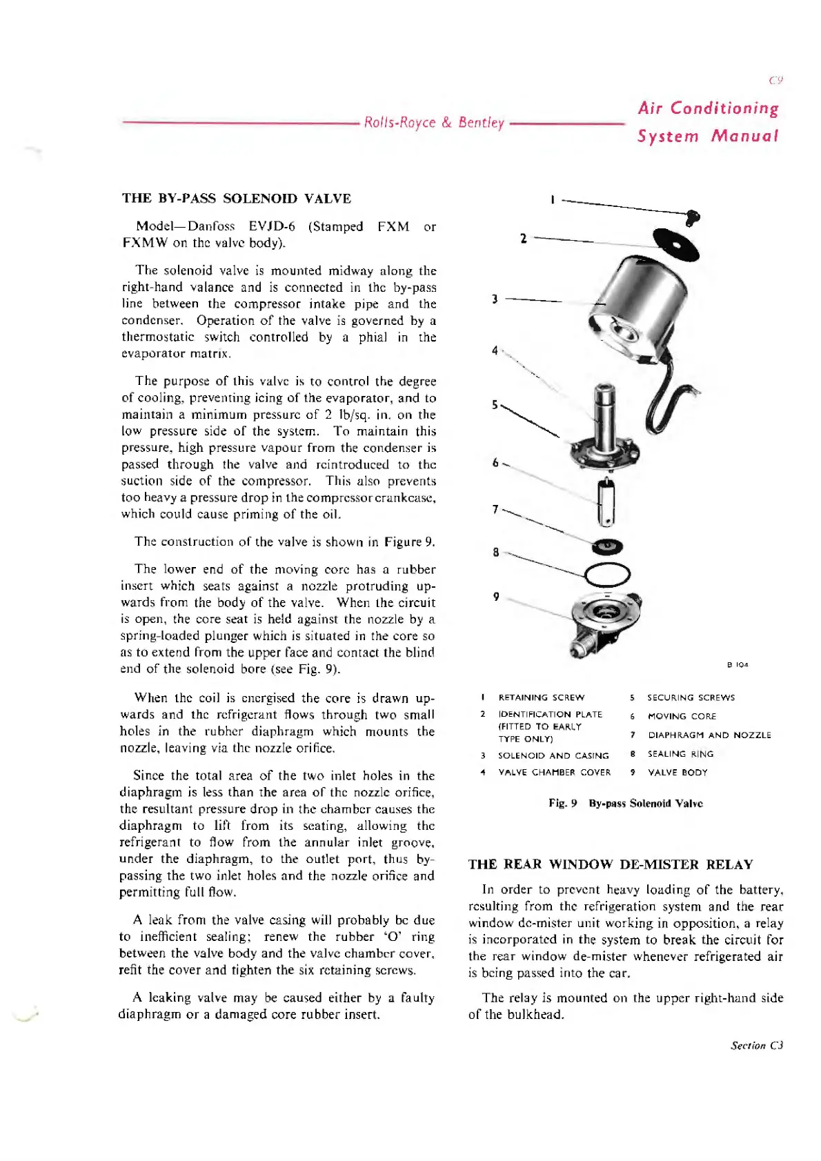
The
construction
of
the
valve
is
shown
in
Figure
9.
The
lower end
of
the
moving core
has
a
rubber
insert which seats against a nozzle
protruding
up-
wards
from the body
of
the
valve. When
the
circuit
is
open, the
core
seat
is
held against the nozzle by a
spring-loaded plunger which
is
situated
in
the core so
as to
extend
from
the
upper
face and
contact
the
blinc1
end
of
the solenoid bore (see Fig.
9)
.
When
the
coil is energised
the
core
is
drawn
up-
wards
and
the refrigerant flows
through
two small
holes in
the
rubhcr
diaphragm
which
mounts
the
nozzle, leaving via the nozzle orifice.
Since
the
total area
of
the
two inlet holes in
the
diaphragm
is
less
than
the
area
of
the nozzle orifice,
the
resultant pressure
drop
in the
cham
bcr
causes
the
diaphragm
to
lift
from
its seating, allowing
the
refrigerant to flow from the
annular
inlet groove,
under
the di
aphragm,
to the outlet
port,
thus by-
passing the two inlet holes
and
the nozzle orifice
and
perm
i
tt
ing full flow.
A leak
from
the valve casing will
probably
be
due
to inefficient sealing; renew
the
rubber
'O
' ring
between
the
valve
body
and the valve
chamber
cover,
refit the
cover
and
tighten
the
six retaining screws.
A leaking valve may
be
caused either by a faulty
diaphragm
or
a
damaged
core
rubber
insert.
) -
--
-
4 ·
6
--.
8
9
RETAINING
SCREW
2
IDENTIFICATION
PLATE
(FITTED
TO
EAisL Y
TYPE
ONLY)
3
SOLENOIO
AND
CASING
e
104
5
SECURING
SCREWS
MOVING
CORE
7
DIAPHRAGM
AND
NOZZLE
B SEALING
isl
NG
~
VALVE
CHAMBER
COVER 9
VALVE
BODY
Fig. 9
By-p11ss
Solenoid Valve
THE REAR WINDOW DE-MISTER RELAY
In
order
to prevent heavy loading
of
the
battery,
resulting from
the
refrigeration system and the
rear
window de-mister unit working in
opposition,
a relay
is
incorporated
in
the system to
break
the
circuit for
the
rear
window de-mister whenever refrigerated air
is
bci ng passed
in
to the car.
The relay is
mounted
on the
uppcr
right-hand
side
of
the
bulkhead.
Section
CJ