C/5
---------
----
Rolls-Royce
& Bentley
--
---
- -
Air
Conditioning
System
Manual
CONDENSER
The
condenser matrix
is
situated between the
radiator
matrix
and the
intake
grille (see Fig. 14).
Its purpose is
to
cool refrigerant gas delivered by the
compressor
and
condense
it;
the liquid refrigerant
then passes into the receiver.
The
matrix comprises two banks, each
of
sixteen
horizontal
tubes. A single inlet pipe conveys com-
pressed refrigerant
to
a 'Tee'
junction
at
the head
of
the matrix. This
junction
supplies the
two
banks
independently.
At
the
base
of
the matrix
another
junction
connects
them
to
the single outlet.
A by-pass pipe to the solenoid valve permits high
pressure
vapour
to
flow back
to
the suction side
of
the compressor when the valve
is
open.
THE RECEIVER
The
receiver
is
a steel container
of
welded con-
struction, secured by three bolts to a bracket forward
of
the frame
front
cross-member (see Fig. 15).
The
inlet pipe union is situated
at
the
top
of
the
container;
the
outlet
union
is
positioned midway
down
the
right-hand
end-face. Inside the receiver,
a
pipe
attached to the outlet union bends
downward
to
the base
of
the unit
in
order
to ensure
that
liquid
refrigerant only will pass
to
the drier.
A fusible plug, inserted
at
the base
of
the
unit,
prevents explosion in
the
event
of
fire. Under no
circumstances must
thi.<;
he replaced by a solid plug.
I
SIGHT
GLASS
2 RECEIVER
3
DRIER
Fig.
15
Drier, Receiver and Sight Glass
THE
DRIER
The
drier
unit is
mounted
below the right-hand
front
apron
(see Fig. 15),
and
has a sight glass
attached
to
the
elbow
at
the
outlet
end.
The
drier unit consists
of
a steel
tubular
shell fitted
with
flared connections
at
the inlet
and
outlet.
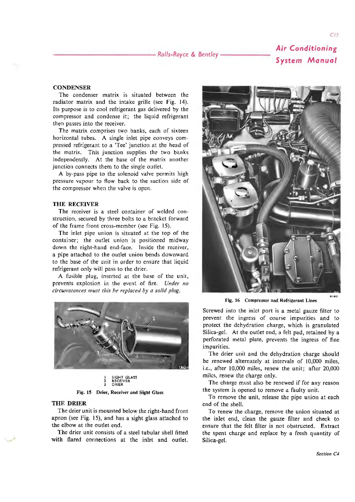
8180
Fig. 16 Compressor and Refrigerant Lines
Screwed
into
the inlet
port
is
a metal gauze filter
to
prevent the ingress
of
coarse impurities
and
to
protect the dehydration charge, which
is
granulated
Silica-gel.
At
the outlet end, a felt pad, retained
by
a
perforated metal plate, prevents the ingress
of
fine
impurities.
The
drier unit
and
the
dehydration
charge should
be
renewed alternately
at
intervals
of
10,000 miles,
i.e.,
after
10,000 miles, renew the unit;
after
20,000
miles, renew the charge only.
The
charge must also be renewed
if
for
any
reason
the system is opened
to
remove a faulty unit.
To
remove the unit, release the
pipe
union
at
each
end
of
the shell.
To
renew the charge, remove the union
situated
at
the inlet end, clean the gauze filter
and
check
to
ensure
that
the felt filter
is
not
obstructed.
Extract
the
spent
charge and replace
by
a fresh
quantity
of
Silica-gel.
Section C4