Do you have a question about the ROOTECH Accura 2300 and is the answer not in the manual?
Illustrates the initial setup steps for the Accura 2350 model.
Shows the initial setup steps for the Accura 2300 model.
Details the short and long press operations of the SET button on the Accura 2350.
Outlines the sequence of menu items for configuring the 3-phase module.
Outlines the sequence of menu items for configuring the 1-phase module.
Describes how to set the unique identification number for the CT5A module.
Details the process for setting the Current Transformer ratio for the CT5A module.
Explains setting phase sequence and load direction for 3-wire/4-wire CT5A connections.
Covers the setup of the identification number for general 3-phase modules.
Details setting phase sequence and load direction for 3-phase wiring configurations.
Explains the procedure for setting the identification number for single-phase modules.
Details setting wiring and load direction for single-phase connections.
Describes how to set the phase sequence for single-phase wiring.
Covers setting the identification number for the 1PSCSH model.
Details setting wiring and load direction for the 1PSCSH model.
Explains short/long press functions of ESC, SETUP, EVENT, and ENTER buttons.
Lists main setup categories: Meter, Event, Module ID, and Information.
Presents an overview of available wiring connection modes for Accura 2300.
Wiring diagram for direct connection in a three-phase, 4-wire system.
Wiring diagram for direct connection in a three-phase, 3-wire system.
Wiring diagram for 3PT connection in a three-phase, 4-wire system.
Wiring diagram for 2PT connection in a three-phase, 3-wire system.
Wiring diagram for direct connection in a single-phase, 3-wire system.
Wiring diagram for direct connection in a single-phase, 2-wire system.
Wiring diagram for 2PT connection in a single-phase, 3-wire system.
Wiring diagram for 1PT connection in a single-phase, 2-wire system.
Configuration of the primary voltage rating for Potential Transformers.
Configuration of the secondary voltage rating for Potential Transformers.
Assigning modules to phases in a 3-wire/4-wire system with three modules.
Assigning modules to phases in a 3-wire system with two modules.
Explains parameters like communication, conflict, and total counts for module IDs.
Details the steps for updating module identification information.
The Accura 2300/2350 series is a comprehensive energy monitoring system designed for both human and nature's energy solutions. This quick setup guide outlines the essential steps for configuring the devices, emphasizing ease of use and efficient operation. The system comprises two main components: the Accura 2350 modules, which are current transformers (CTs) with integrated measurement capabilities, and the Accura 2300 main unit, which acts as the central display and control interface.
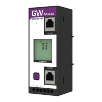
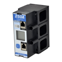
The Accura 2350 modules are designed to measure current and, in some configurations, voltage, providing real-time data on energy consumption. These modules come in various types, including single-phase (1P) and three-phase (3P) configurations, with different current ratings (e.g., 60A, 125A, 250A, 400A) and CT types (e.g., CT Inside, CT5A). They are equipped with RJ12 ports for communication with the Accura 2300 main unit, allowing for a modular and scalable energy monitoring system. Each Accura 2350 module can be individually configured for its ID, phase sequence, load direction, rated current, and leakage current settings, ensuring accurate data collection tailored to specific electrical installations.
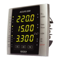
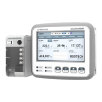
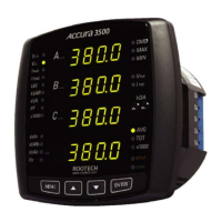
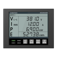
The Accura 2300 main unit serves as the central hub for the system. It receives data from the connected Accura 2350 modules and displays key electrical parameters such as voltage (V L-L), current (I RMS), active power (P), and total energy (E). The Accura 2300 features a clear LCD display and a user-friendly interface with dedicated buttons for navigation, setup, event viewing, and data entry. It supports various wiring modes, including three-phase 4-wire, three-phase 3-wire, single-phase 3-wire, and single-phase 2-wire connections, accommodating a wide range of electrical systems. The main unit also allows for the configuration of PT (Potential Transformer) ratings, which are crucial for accurate voltage measurements in systems with external voltage transformers. Furthermore, it provides functionalities for managing module IDs, detecting communication conflicts, and updating module information, ensuring robust system operation.
The Accura 2300/2350 system is designed for intuitive setup and operation. The quick setup guide provides a clear, step-by-step procedure, starting with the configuration of the Accura 2350 modules (Step 1) and then proceeding to the Accura 2300 main unit (Step 2).
Each Accura 2350 module has a single "SET" button for configuration.
The setup menu for the Accura 2350 modules is organized by module type (3P Module for three-phase and 1P Module for single-phase).
Specific setup examples are provided for different module types:
The Accura 2300 main unit features multiple buttons: ESC, SETUP, EVENT, and ENTER.
The Accura 2300's setup menu is categorized into Meter, Event, A2350 Module ID, and Information.
This feature allows users to assign Accura 2350-1PSCSH modules to specific phases (L1, L2, L3) and configure their IDs for three-phase systems. The setup process involves entering the group assignment menu, selecting the desired phase (a, b, or c), moving to the next digit, changing the value, and finally completing the setup.
The Accura 2300 can update the module ID information of connected Accura 2350s. This process involves navigating to the "IduP" option in the A2350 Module ID menu, long-pressing ENTER to initiate the update (IduP blinks), and then long-pressing ESC to return to the display mode once the update is complete (IduP stops blinking).
While the quick setup guide primarily focuses on initial configuration, several aspects contribute to the system's maintainability:
In summary, the Accura 2300/2350 system offers a robust and user-friendly solution for energy monitoring, with a focus on flexible configuration, clear operational procedures, and built-in features that support both initial setup and long-term maintenance.
| Category | Infrared Thermometer |
|---|---|
| Measurement Range | -50°C to 2300°C (-58°F to 4172°F) |
| Response Time | 500ms |
| Spectral Response | 8-14μm |
| Distance to Spot Ratio | 50:1 |
| Operating Temperature | 0°C to 50°C (32°F to 122°F) |
| Resolution | 0.1°C / 0.1°F |
| Emissivity | Adjustable 0.10-1.00 |
| Display | LCD with backlight |
| Battery Type | 9V Battery |
| Battery Life | 12 hours (continuous use) |