Do you have a question about the Ropex RESISTRON RES-5010 and is the answer not in the manual?
Specifies intended use of the temperature controllers and compliance with instructions.
Details requirements for safe and reliable heatsealing band operation, including TCR.
Discusses the need for a suitable impulse transformer and installation precautions.
Highlights the importance of using the correct current transformer for system integrity.
Mandates the use of an original ROPEX line filter for standard compliance.
Lists the standards and directives the controller complies with.
Outlines the warranty period and conditions for the device.
Outlines potential causes of unwanted overheating in heatsealing bands.
Explains the principle of heatsealing band temperature control using resistance.
Lists various potential fault causes leading to dangerous overheating.
Provides essential measures to prevent overheating in the heatsealing system.
Details faults and their detection methods using different system components.
Discusses remaining risks that may lead to undetected overheating even with monitoring.
Lists compatible accessories to optimize the monitoring device for specific applications.
Describes available modifications (MODs) for implementing special applications.
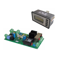
Provides step-by-step instructions for installing the RESM-5 monitoring device.
Details the process of integrating RESM-5 with RESISTRON controllers for alarm evaluation.
Illustrates the electrical connections required for the RESM-5 unit.
Specifies requirements for connecting the device to the power supply.
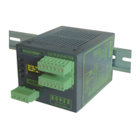
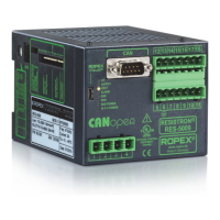
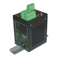
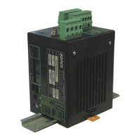
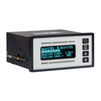
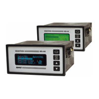
Identifies key components and features of the RESM-5 unit.
Explains how to configure the device's settings for optimal operation.
Details the importance and properties of the heatsealing band in the control loop.
Guides through the initial steps for starting up and testing the monitoring unit.
Instructions for restarting the unit after replacing the heatsealing band.
Identifies and explains the function of LEDs and control buttons on the unit.
Describes the various display modes and messages shown by the unit.
Explains how error messages are displayed and what they indicate.
Details how to navigate through the device's menu system.
Presents a visual overview of the device's menu hierarchy.
Lists and describes the available menu steps and their setting ranges.
Explains how to set and monitor the maximum temperature limit.
Describes how actual temperature is displayed and outputted as an analog signal.
Details the automatic zero calibration process for accurate temperature measurement.
Explains the function and behavior of the external ALARM-IN/RESET signal.
Describes how to disable the AUTOCAL function to prevent accidental calibration.
Allows switching the temperature display between Celsius and Fahrenheit.
Details how to lock the Configuration menu to prevent unauthorized changes.
Explains how to adjust the brightness of the OLED display.
Describes the unit's behavior when the supply voltage drops below tolerance.
Shows how to access unit details like firmware version and serial number.
Shows how to access unit details like firmware version and serial number.
Details the interface for system diagnostics and process visualization.
Explains features for error detection, diagnosis, and alarm output.
Explains features for error detection, diagnosis, and alarm output.
Provides a comprehensive list of error codes, their causes, and corrective actions.
Maps fault areas to explanations and possible causes for the main controller.
Allows saving and restoring custom device configurations.
| Control range | 0-100% |
|---|---|
| Accuracy | ± 0.5 % |
| Protection class | IP20 |
| Input voltage | 230 V AC, 50/60 Hz |
| Operating temperature | 0°C to 50°C |