Do you have a question about the Ropex RESISTRON RES-408 and is the answer not in the manual?
Legal statement regarding content ownership and rights.
Specifies approved applications and risks of misuse for the temperature controller.
Details alloy, TCR, and plating requirements for heatsealing bands.
Outlines requirements for impulse transformers and installation safety.
Specifies the use of original ROPEX current transformers for system integration.
Mandates ROPEX line filters for CE conformity and EMC directives.
Recommends regular terminal inspection and cleaning with dry compressed air.
Instructions for storing and transporting the device in its original carton.
Guidelines for environmentally sound disposal according to EU directives.
Declares conformance with cited standards and directives for the RESISTRON controller.
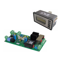
Lists optional accessories like temperature meters, filters, and transformers.
Details various modifications (MODs) for special application requirements.
Step-by-step guide for installing the RESISTRON temperature controller.
Illustrates installation with wiring diagram and key connection points.
Details power supply connection, protection, and transformer wiring.
Explains the function and installation of line filters for EMC compliance.
Describes the integral role and connection of the current transformer.
Provides a standard wiring diagram for the RES-408 controller connections.
Shows the specific wiring diagram for using a booster connection (MOD 26).
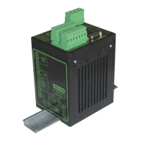
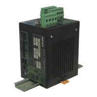
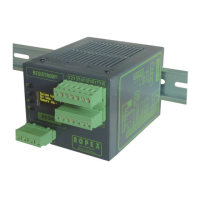
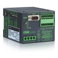
Identifies the main components of the RES-408 controller and terminal.
Details configuration of secondary voltage, current, and DIP switches.
Discusses band properties, burn-in, and replacement procedures.
Step-by-step guide for the first-time startup of the controller.
Guides on restarting the controller after replacing the heatsealing band.
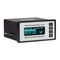
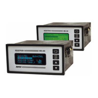
Explains the LEDs, buttons, and terminal interface of the controller.
Describes power-up messages, home position, settings menu, and error messages.
Explains how to navigate controller menus with and without alarms.
Visual representation of the controller's menu flow and options.
Details key menu steps like Home, Hand, SealHeat, and Preheat.
Explains AutoCal, Autocomp, and Hold mode functions within the menus.
Covers alarm menu functions and setting the heatsealing temperature.
Describes how actual temperature is displayed and output as an analog signal.
Details the AUTOCAL function for automatically adjusting the zero point.
Explains how the heating process is initiated using the START signal.
Explains the PREHEAT function for shortening heating time in critical applications.
Explains the different settings for the HOLD mode of the display.
Describes how to switch between Celsius and Fahrenheit display units.
Explains setting the length of measuring impulses via software.
Explains the AUTOCOMP function for phase angle compensation.
Describes temperature diagnosis activated via visualization software.
Explains the heatup timeout function activated via software.
Describes errors indicated by terminal display and their causes.
Explains standby mode activation due to low line voltage.
Describes the diagnostic interface and visualization software connectivity.
Explains how the controller monitors the system and provides alarm indications.
Details error codes, their meanings, and required corrective actions.
Explains fault areas with diagrams and possible causes for troubleshooting.
| Brand | Ropex |
|---|---|
| Model | RESISTRON RES-408 |
| Category | Controller |
| Language | English |