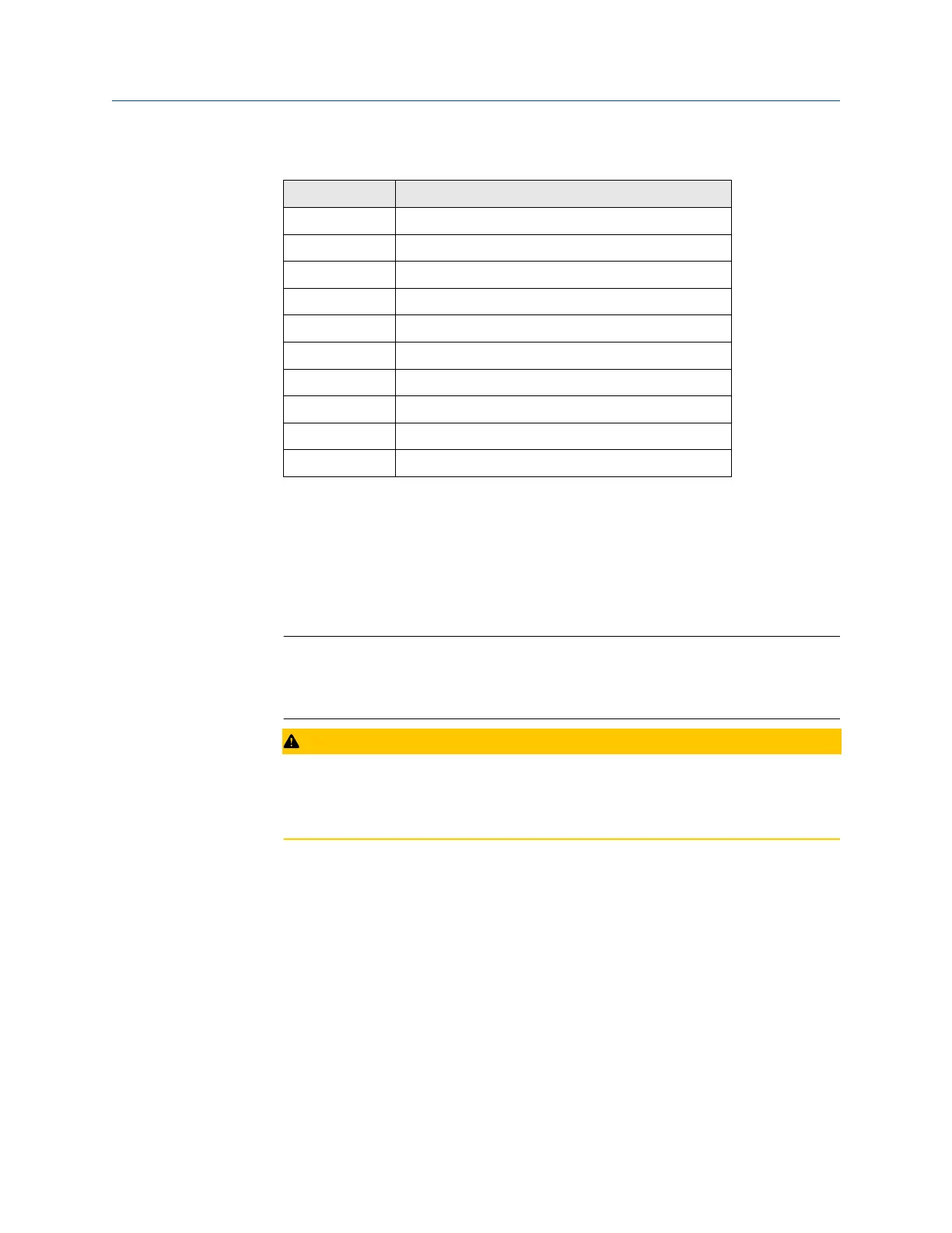
Table 2-1: Discrete Digital Inputs TB7
TB7 Function
Pin 1 DI1
Pin 2 DI-RTN
Pin 3 DI2
Pin 4 DI-RTN
Pin 5 DI3
Pin 6 DI-RTN
Pin 7 DI4
Pin 8 DI-RTN
Pin 9 DI5
Pin 10 DI-RTN
Wire a ROC800 digital input (DI) module
To connect the ROC800 DI module to a field device, do the following:
Procedure
1. Expose the end of the wire to a maximum length of ¼-in. (6.4 mm).
Note
Twisted-pair cables are recommended for in/out (I/O) signal wiring. The module’s
terminal blocks accept wire sizes between 12 and 22 American wire gauge (AWG).
Allow some slack when making connections to prevent strain.
CAUTION
Failure to follow this precaution may cause a short circuit and damage equipment.
Allow only a minimum exposure of bare wires to prevent short circuits.
2. Insert the exposed end into the clamp beneath the termination screw.
3. Tighten the screw.
Installation and start-up Quick Start Guide
July 2020 00825-0100-3770
36 Emerson.com/Rosemount