EasyManua.ls Logo

Ross TC700MC User Manual

Ross TC700MC
44 pages
To Next Page IconTo Next Page
Page #1 background imageLoading...
Page #1 background image
MN700-MC0010
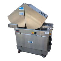
MODEL TC700MC
TENDERIZER
MADE IN USA
Ross Industries, Inc.
Midland, Virginia 22728
Phone: (540) 439-3271
(800) 336-6010
Fax: (540) 439-2740

Questions and Answers:

Ross TC700MC Specifications

General IconGeneral
BrandRoss
ModelTC700MC
CategoryCommercial Food Equipment
LanguageEnglish

Summary

WARRANTY POLICY

INTRODUCTION

SAFETY FIRST!

DAILY CLEANING PROCEDURE

1 SPECIFICATIONS

ELECTRICAL SPECIFICATIONS

Details voltage, frequency, current, and power cord specifications for the tenderizer.

2 DESCRIPTION

2.1 MECHANICAL DESCRIPTION

Explains the mechanical operation of the tenderizer head, blades, and conveyor drive.

2.2 ELECTRICAL DESCRIPTION

Describes the electrical control system components and their location within the tenderizer.

2.2 ELECTRICAL CONTINUED

Details the power flow, starter, safety sensors, and head adjusting motor circuit operation.

3 INSTALLATION

3.1 UNCRATING INSTRUCTIONS

Instructions for safely removing the tenderizer from its shipping crate and skid.

3.2 INSTALLATION GUIDELINES

Guidance on positioning the tenderizer, floor requirements, and caster care.

3.3 ELECTRICAL REQUIREMENTS

3.4 POWER PHASING

3.5 INSTALLATION CHART

4 SPARE PARTS

5 ILLUSTRATIONS

5.1 GUARD/SAFETY SWITCH

Details the components and part numbers for the guard and safety switch assembly.

5.2 HEAD CARRIER ASSEMBLY

Lists components and part numbers for the head carrier assembly of the tenderizer.

5.3 HEAD ASSEMBLY

Provides a breakdown of the head assembly, including blades and retainers.

5.4 CONVEYOR DRIVE ASSEMBLY

Details the components and part numbers for the conveyor drive assembly.

5.5 CONVEYOR ASSEMBLY

Lists components and part numbers for the conveyor assembly, including rails and belt supports.

5.6 MOTOR/REDUCER ASSEMBLY

Details the components and part numbers for the motor and reducer assembly.

5.7 CAM DRIVE ASSEMBLY

Lists components and part numbers for the cam drive assembly.

5.8 CAM ASSEMBLY

Provides a breakdown of the cam assembly components and their part numbers.

5.9 RETURN SPRING/CAM ASSEMBLY

Details components and part numbers for the return spring and cam assembly.

5.10 TOGGLE CLAMP/RETURN SPRING ASSEMBLY

Lists components and part numbers for the toggle clamp and return spring assembly.

5.11 MAIN FRAME/ROCKER BAR CAM FOLLOWER

Details components and part numbers for the main frame and rocker bar cam follower.

6 OPERATION

6.1 MACHINE OPERATION

Step-by-step instructions for operating the tenderizer safely and effectively.

6.2 CLEANING AND BLADE REPLACEMENT

Provides daily cleaning procedures and instructions for replacing tenderizer blades.

6.3 HEAD ASSEMBLY INSTALLATION

Illustrates the process of installing the head assembly onto the tenderizer.

7 MAINTENANCE

7.1 INSPECTION

Outlines the nature and frequency of inspections for bent blades and height controls.

7.2 LUBRICATION

Details lubrication requirements based on operating hours and frequency.

7.3 ADJUSTMENTS/SPECIFIC REPAIRS

Covers adjustments for conveyor link belt stretch and height adjusting mechanism.

7.3.2 HEAD HEIGHT ADJUSTMENT

Explains how to check and adjust the clearance between blades and the conveyor belt.

7.3.3 HEIGHT ADJUST CAM MECHANISM

Details the operation and potential issues of the height adjust cam mechanism.

7.3.4 RESET PAD/PLATE CLEARANCE

Explains the function and importance of reset pads and their clearance.

7.3.5 TOGGLE RING REPLACEMENT

Step-by-step instructions for replacing the toggle ring assembly.

8 TROUBLESHOOTING

TROUBLESHOOTING CHART

A chart detailing common problems, their causes, and recommended remedies.

9 WIRING/SCHEMATIC

Related product manuals