After the head height has been set correctly, the clearance between the tops of the blade assemblies,
(p5-3, item 6), and the reset pad, (p5-2, item 2), should be checked. To do this, run the head assembly
to the top of the stroke. Open the pivoting guard, (p5-1, item 1), and look for a space between the blade
assembles tops and the bottom of the reset pad. Hold onto each retainer bar, (p5-3, item 3), in turn and
try to move the head assembly magnet carrier within its’ mounting slot. The head should move around
easily without the blade assemblies touching the reset pad. There should be no greater clearance than
approximately .06 inches, (1.5 mm), between the tops of the blades and the reset pads.
To correct clearance add or delete shim washers between the top of the reset plate studs, (p5-2, item
16) and the reset plate. Shim washer numbers are:
• 11451009................................................. Washer, flat 3/4 id x .032 thk
• 11450116................................................. Washer, flat 3/4 id x .092 thk
There may already be washers on top of the reset posts to adjust the height of the reset plate. The 700M
is carefully adjusted at the factory. If, for any reason, the reset plate, head frame or guide frame is
removed from the machine, be sure to keep track where each shim washer goes. During reassemble,
make sure that the washers go back in exactly the same position.
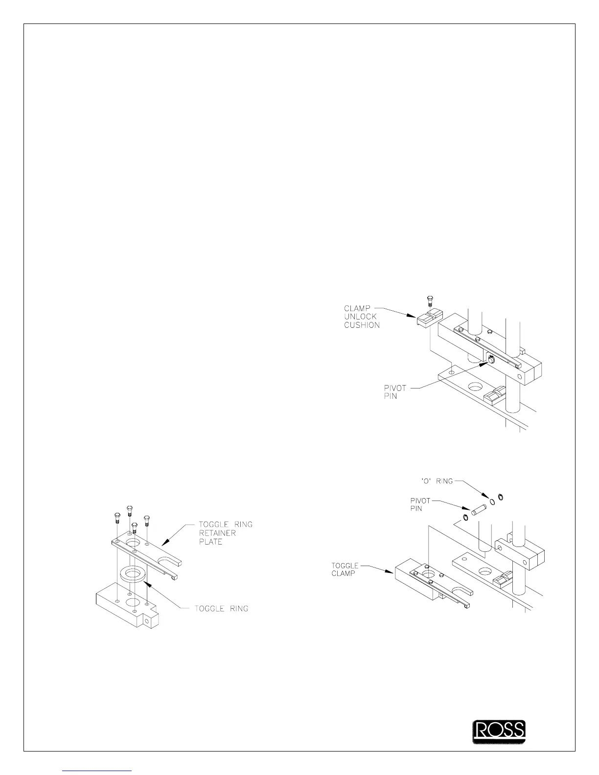
7.3.5 TOGGLE RING REPLACEMENT
A. Disconnect the machine power cord. Remove the side
cover panel.
B. Rotate motor coupling (in direction of arrow) until head
assembly is in full down position.
C. Remove unlock cushion
D. Remove pivot pin, turn toggle clamp and remove from
shaft
E. Remove toggle ring retainer plate and toggle ring
F. Install new toggle ring; replace toggle ring retainer
plate.
NOTE - Always install new toggle rings on both sides.
G. Replace toggle clamp. Install pivot pin
Make sure snap rings are in position
H. Check the snap ring position on the guide uprights. There should be one snap ring above and one
below the clamp pivot, the snap rings go in the lower two grooves on the guide uprights
MN700-MC0010
7-5