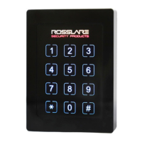
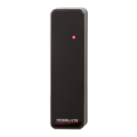
AY-K6255
MIFARE Classic CSN Smart Card Reader (Rev. A)
Installation and User Manual
1
1. Introduction
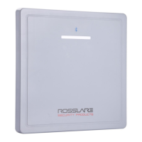
The AY-K6255 is a contactless smart card reader for use in access
control system solutions. This reader reads the Card Serial Number
(CSN) of MIFARE Classic® EV1 (ISO14443A) credentials.
The standard readers output the Wiegand CSN data in 26-bit format.
Other Wiegand formats are available upon request.
The reader is approved by the Institute for Science and Halacha for use
on the Sabbath.
Figure 1: AY-K6255
2. Technical Specifications
2.1 Electrical Characteristics
Power Supply Type
Regulated
Operating Voltage Range
8 to 16 VDC
Current @ 12 V
Standby: 55 mA, max: 80 mA
Read Range*
5 cm (2.0 in.)
LED/Buzzer Controls**
Dry Contact, N.O.
Tamper Output**
Open collector, active low, max. sink current
16 mA
Maximum Cable Distance
to Controller
Wiegand: 150 m (500 ft) with 18-AWG cable
OSDP (RS-485): 1,200 m (4,000 ft) with 2x2
18-AWG twisted shielded cable
* Measured using a Rosslare MIFARE Classic EV1 (ISO card). Read range with
other credential technologies may vary. Range also depends on electrical
environment and proximity to metal.
** Control lines are factory programmable and can be custom configured upon
request.
2.2 Environmental Characteristics
Operating Temp. Range
-35°C to 66°C (-31°F to 150°F)
Operating Humidity Range
0 to 95% (non-condensing)
Outdoor Usage
Weather-resistant, UV-resistant, meets IP65,
epoxy-potted, suitable for indoor and outdoor
use
2.3 Physical Characteristics
Dimensions (H x W x D)
80.5 x 40.5 x 14.7 mm (3.2 x 1.6 x 0.6 in.)
Weight
73 g (2.6 oz)
3. Installation
3.1 Installation Kit
The installation kit consists of the following items to be used during
the installation procedure:
1 backplate
1 self-adhesive mounting label template
1 metal clip
2 pan head mounting screws and screw anchors
1 Torx key tool and one Torx security screw
3.2 Mounting
Before mounting, you should determine the best location for the
reader.
1. Peel off the back of the self-adhesive mounting label template and
place it at the required mounting location.
2. Using the template as a guide, drill two holes (hole size and
position is indicated on the mounting template) for mounting the
reader onto the surface.
3. Insert a screw anchor into each hole.
4. Drill a 10-mm (7/16”) hole for the cable. If mounting on metal,
place a grommet or electrical tape around the edge of the hole.
5. Wire the reader to the host as described in Section 3.3. A linear
type power supply is recommended.
6. Remove the security screw from the bottom of the unit.
7. Remove the reader's snap-off front cover.
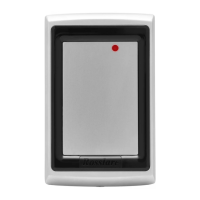
8. Align the two holes of the backplate and of the reader with those
drilled in the wall and firmly attach the reader to the wall with two
screws (Figure 2).
Figure 2: Mounting Screws
9. Relocate the front cover onto the reader.
10. Return the security screw to the bottom of the unit.
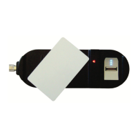
11. Insert the metal clip into the slot at the base of the backplate
(Figure 3).
Figure 3: Metal Clip