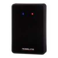
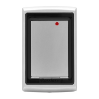
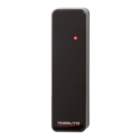
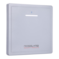
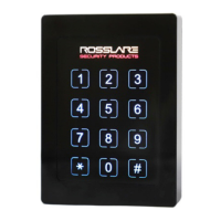
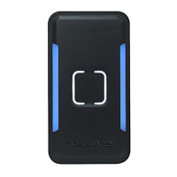
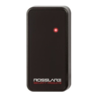
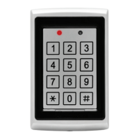
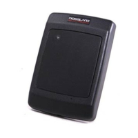
AY-x12C Series
Rosslare PROX Readers
Installation Manual
1
1. Introduction
The AY-x12C is a series of RFID proximity card readers to be installed
for use with access control systems.
The AY-x12C series reads the proximity card and transmits its data to
the access control system, using Wiegand 26-Bit and Clock & Data
outputs.
Figure 1: AY-x12C Series
2. Technical Specifications
2.1 Electrical Characteristics
Specification AY-M12C AY-H12C AY-L12C AY-K12C
AY-Q12C
Power Supply Type
Linear (recommended)
Operating Voltage
Range
5–16 VDC
Absolute Maximum
(non-operating)
18 VDC
Current @ 12V
Standby: 60 mA
Maximum: 120 mA
Maximum Read
Range*
10 cm (4 in.) 8 cm
(3.2 in.)
4 cm
(1.6 in.)
All Control Inputs
Dry Contact, N.O.
Tamper Output
Open collector, active low, max. sink current 16 mA
Maximum Cable
Distance to
Controller
18 AWG – 150 m (500 ft)
20 AWG – 90 m (300 ft)
RF Modulation
ASK, 125 kHz
* Measured using a Rosslare proximity card or equivalent. Range also depends on
installation environment, reader voltage, and proximity to metal.
2.2 Environmental Characteristics
Specification AY-M12C AY-H12C AY-L12C AY-K12C AY-Q12C
Operating
Temp. Range
-31°C to 63°C (-25°F to 145°F)
Operating
Humidity Range
0 to 95% (non-condensing)
2.3 Physical Characteristics
Model Dimensions
(H x W x D)
Weight
AY-M12C
89 x 89 x 15 mm
(3.5 x 3.5 x 0.6 in.)
109 g
(3.9 oz.)
AY-H12C
110 x 75 x 15 mm
(4.3 x 3.0 x 0.6 in.)
100 g
(3.5 oz)
AY-L12C
145 x 43 x 20 mm
(5.7 x 1.7 x 0.8 in.)
116 g
(4.1 oz)
AY-K12C
80 x 40 x 12.8 mm
(3.2 x 1.6 x 0.5 in.)
70.5 g
(2.5 oz)
AY-Q12C
120 x 76 x 20 mm
(4.7 x 3.0 x 0.8 in.)
480 g
(17.0 oz)
3. Installation
Card readers are to be used with control panels whose power
supply is UL Listed Class 2 or equivalent.
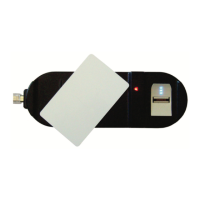
3.1 Installation Kit
The installation kit consists of the following items to be used during
the installation procedure:
One self-adhesive mounting label template
Two pan head mounting screws and screw anchors
One pin Torx key tool
One pin Torx security screw
3.2 Mounting the AY-x12C Reader
Before mounting, you should determine the best location for the
reader.
1. Peel off the back of the self-adhesive mounting label template and
place it at the required mounting location.
2. Using the template as a guide, drill two holes (hole size and
position is indicated on the mounting template) for mounting the
reader onto the surface.
3. Insert a screw anchor into each hole.
4. Drill a 10-mm (7/16”) hole for the cable. If mounting on metal,
place a grommet or electrical tape around the edge of the hole.
5. Wire the reader to the host as described in Section 4. A linear type
power supply is recommended.
6. Refer to Figure 2 for correct use of mounting screws.
Figure 2: Correct Use of Mounting Screws
AY-H12C AY-L12C AY-K12C AY-Q12C