Do you have a question about the Rosslare AC-Q74 and is the answer not in the manual?
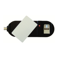
Lists items included in the AC-Q74 package.
Specifies necessary external components for AC-Q74 operation.
Details voltage, current, and LED specifications for the AC-Q74.
Outlines operating temperature and humidity limits.
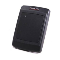
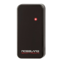
Provides dimensions and weight of the AC-Q74 unit.
Instructions for physically attaching the AC-Q74 unit to a mounting surface.
Details the electrical connections and wire color guide for the AC-Q74.
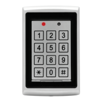
Describes the default operating mode with green LED indication.
Explains the bypass mode, indicated by an orange LED.
Details the secure mode, indicated by a red LED, requiring dual codes.
Procedure to switch the unit's operation from Normal to Secure mode.
Procedure to switch the unit's operation from Secure to Normal mode.
Procedure to switch the unit's operation from Normal to Bypass mode.
Procedure to switch the unit's operation from Bypass to Normal mode.
Steps to access the AC-Q74's programming menu system.
Instructions on how to safely leave the programming mode.
Procedure to set or modify the first lock strike code for testing.
Procedure to set or modify the second lock strike code for testing.
Process for changing the main programming access code.
How to set or change the code for Normal/Secure mode transitions.
Instructions for setting or modifying the Normal/Bypass mode code.
Configures Fail Safe/Secure operation and lock strike release time.
Details on enrolling user codes, including primary/secondary code concepts and methods.
Procedures for removing user codes using standard or code search methods.
Resets all user codes and settings to the original factory defaults.
Steps to recover or reset a forgotten programming code.
Procedure for resetting a lost Normal/Secure access code.
Overview of the PC-25T power supply and its main functionalities.
Lists the electrical input, output, and current ratings for the power supply.
Defines the operating temperature and humidity ranges for the power supply.
Provides physical dimensions and weight details for the power supply unit.
Offers guidance on cable types and maximum distances for wiring.
Diagram showing hole spacing for mounting PCBs.
Details the PS-A25T enclosure, including its built-in transformer and speaker.
Describes PS-C25T/25TU enclosures with speaker, transformer, and battery space.
Schematic illustrating connections for PC-25T and its enclosures.
| Brand | Rosslare |
|---|---|
| Model | AC-Q74 |
| Category | Card Reader |
| Language | English |