Do you have a question about the Rotenso KASI K26Vi and is the answer not in the manual?
Provides information required for ordering spare parts correctly and promptly.
Details the functions and operation of the remote controller buttons.
Outlines various safety protection mechanisms and their functions.
Explains the operation and temperature settings for the 'Feel' mode.
Describes the compressor frequency control in cooling mode based on temperature difference.
Details the operation of the DRY mode, including fan speed and temperature settings.
Explains heating mode operation, frequency control, and indoor fan motor control.
Details the conditions and process for defrosting the unit.
Explains the overheat protection for the indoor heat exchanger.
Describes the operation and settings for the 'SLEEP' mode.
Explains how to use the emergency operation switch for manual control.
Details the auto-restart function and how to activate it.
Explains how error codes and protection statuses are displayed.
Lists and explains various error codes, protection codes, and failure indicators.
Lists all part numbers and names for the indoor unit models.
Lists all part numbers and names for the outdoor unit models K26Vo and K35Vo.
Provides crucial safety guidelines for the installation process of the air conditioner.
Details safety guidelines and best practices for users of the air conditioner.
Lists prohibitions and safety rules to prevent hazards during operation and maintenance.
Identifies and labels the main components of the indoor unit.
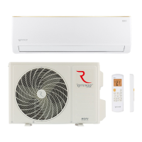
Identifies and labels the main components of the outdoor unit.
Covers essential installation details including connecting pipe length and refrigerant piping.
Provides specifications for selecting appropriate power cords based on appliance amperage.
Details the initial installation procedures for both the indoor and outdoor units.
Step-by-step guide for correctly installing the indoor unit's mounting plate.
Instructions on how to drill holes in the wall for refrigerant piping and drain pipes.
Guides on making electrical connections for the indoor unit.
Explains how to connect the refrigerant piping in different directions.
Provides tips for connecting pipes, including handling caps and bending.
Details the process of connecting the pipes to the indoor unit.
Emphasizes the importance of proper condensed water drainage for installation success.
Covers making electronic connections for the outdoor unit.
Describes how to screw flare nuts to the outdoor unit coupling.
Explains the process of bleeding air and humidity from the refrigerant circuit.
Illustrates the control system diagram for the outdoor unit.
Details the components and structure of the Outdoor Unit's Printed Circuit Board (PCB).
Shows the connection details for the Outdoor Unit's Printed Circuit Board (PCB).
Illustrates the flow of current between the indoor and outdoor units.
Troubleshooting steps for error codes E1 or E2 related to sensors or main PCB.
Troubleshooting steps for error code E6 related to indoor fan motor or main PCB.
Troubleshooting steps for error codes E3, E7, or E8 related to outdoor sensors.
Troubleshooting steps for error codes E0 and E5 related to indoor/outdoor communication.
Troubleshooting steps for error code EA indicating a current sensor fault.
Troubleshooting for error code E9, initially showing P0 or P9, related to drive circuit.
Troubleshooting steps for error code EU indicating a voltage sensor fault.
Troubleshooting steps for error code EE indicating an EEPROM fault.
Flowchart for diagnosing IPM/compressor malfunctions when the compressor doesn't start.
Flowchart for troubleshooting DC overcurrent errors, including valve status and compressor rotation.
Provides resistance and voltage data for indoor and outdoor temperature sensors across various temperatures.
Lists resistance and voltage characteristics for outdoor unit sensors at different temperatures.
| Brand | Rotenso |
|---|---|
| Model | KASI K26Vi |
| Category | Air Conditioner |
| Language | English |