6
dull or dampened sound indicates damage in the disc.
Do not fit the disc on the hub by force.
The central bore diameter should not be changed.
Only use matching discs.
The smallest grinding disc diameter should not be less than 4”.
Any adjustments should not be done unless the machine is switched off and unplugged.
No damaged discs should ever be used!
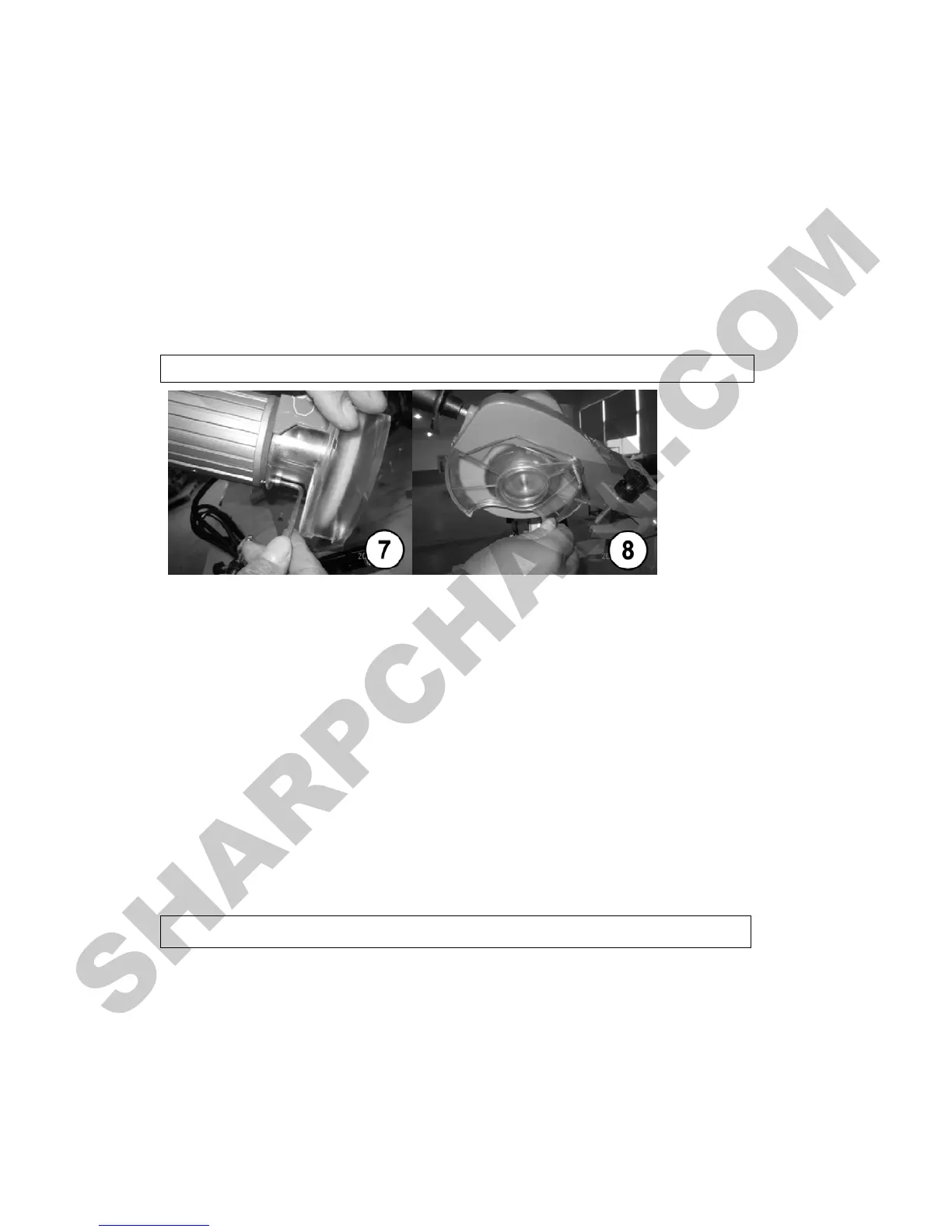
6. Grinding Disk Assembly
After
you have removed the ancillary flange, you can insert the grinding disc in the body from
below. See that the ancillary flange and the disc abut against each other (Fig.7).
To avoid damage to the disc, do not over tighten screws.
The grinding disc on the hub torque is 7 Nm. Use a torque wrench. Now, the grinding disc
guard should be secured (Fig.8).
After installing the disc, run the machine and make sure the disc is not vibrating or spinning
incorrectly. If it is, promptly turn off the machine and unplug the power cord before attempting
to correct the fault.
The machine has a zero voltage circuit breaker, which is disabled during an outage and will
prevent any unexpected restarting of the machine after the power supply is restored.
Using the sharpening stone and clamping plate, sharpen the disc to obtain the required profile.
As always, be careful while working.
7.Clamping the Screw Set Up
Before grinding begins, the chain should be secured between the guides. The tooth to be
sharpened first should be placed against the stop. Watch that the sharpening angle
corresponds to the guide position. The type of chain to be sharpened should be determined
using the sharpening block (if provided) or the table on page 9, where you can find the cutting
thickness, angle and dimensions.