6
5
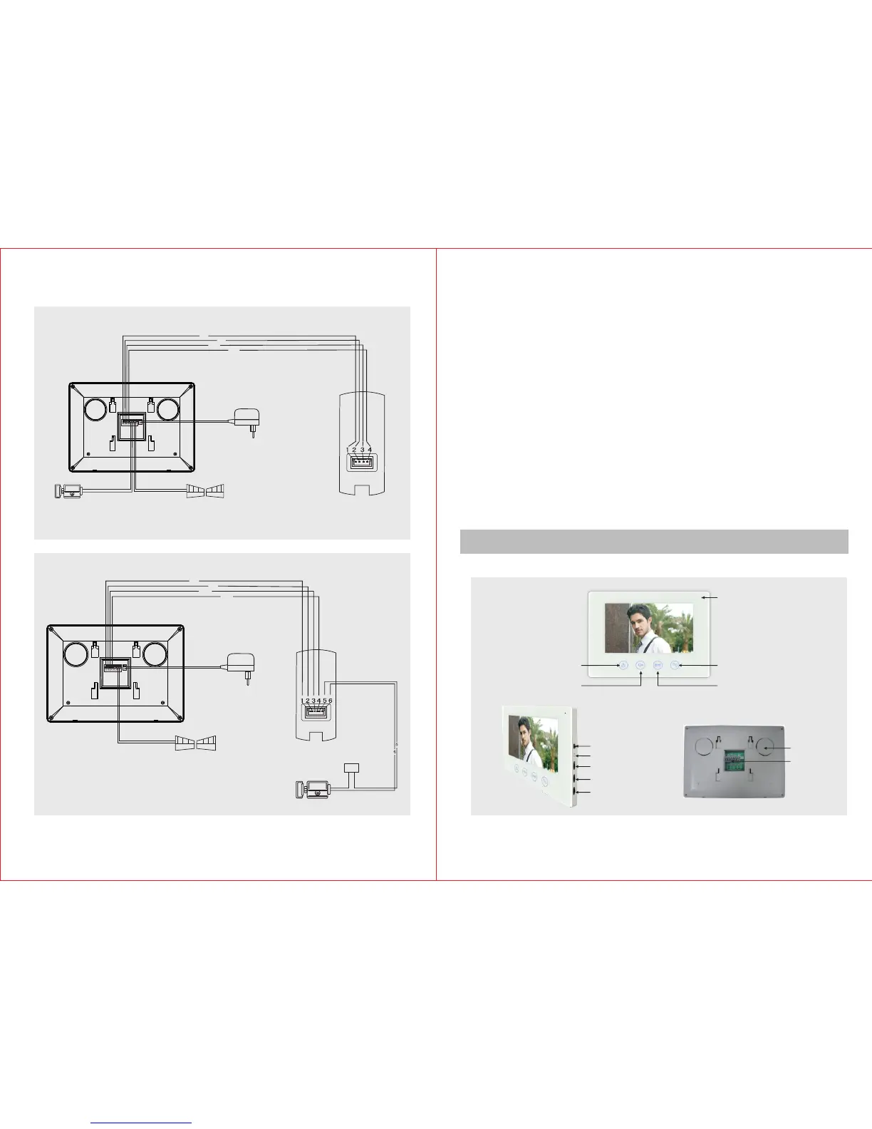
Operation Instruction
Indoor Unit
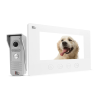
C. Wiring Diagram
Cables:
1.Audio wire
2.Ground wire
3.Video wire
4.Power wire
Outdoor Unit
Electronic-lock
Indoor Unit
Gate Unlock
1
2
3
4
AC100-240V
50HZ/60HZ
DC12V
111
222
333
444555666777 888
Connect the electric lock with indoor unit
Cables:
1.Audio wire
2.Ground wire
3.Video wire
4.Power wire
Outdoor Unit
Electronic-lock
Connect the electric lock with indoor unit
1
2
3
4
AC100-240V
50HZ/60HZ
DC12V
111
222
333
444 555666 777888
+ -
AC 10 0- 24 0V
50 HZ /6 0H Z
DC 12 V
Power
Gate Unlock
Wiring Requirement
1) Generally please use 15m cable to connect indoor unit with outdoor unit.
2
2) RVV4 x 0.5mm connecting wire can be chosen if you want to lengthen it
to 15~50m.
2
3) RVV4 x 0.75mm connecting wire can be chosen if you want to lengthen
it to 50~100m.
2
4) Use RVV2 x 1.0mm connecting wire for the electric-lock.Connect the
wiring terminal 1,2,3,4 of indoor unit with the wiring terminals 1,2,3,4 of
outdoor unit respectively. The wiring terminals 5 and 6 of indoor unit are
2
connected to electric-lock through RVV2x1.0mm wire. The wiring
terminals 7 and 8 of indoor unit are connected to gate lock through
2
RVV2x1.0mm wire.Please refer to the wiring diagram during
connection.
Please choose only one connecting method to do the connection. The
electric lock can be connected either with the indoor unit or with the
outdoor unit. Connecting the electric lock with both the indoor and
outdoor unit at the same time is prohibited.
Melody (L/M/H)
Melody Selection
Brightness
Chroma
Volume
Wiring
Terminal
Speaker
Monitor
Unolock
Microphone
Gate Unlock
Talk