3 Tip the assembly upwards at the edge, and
withdraw it from its location. Disconnect the
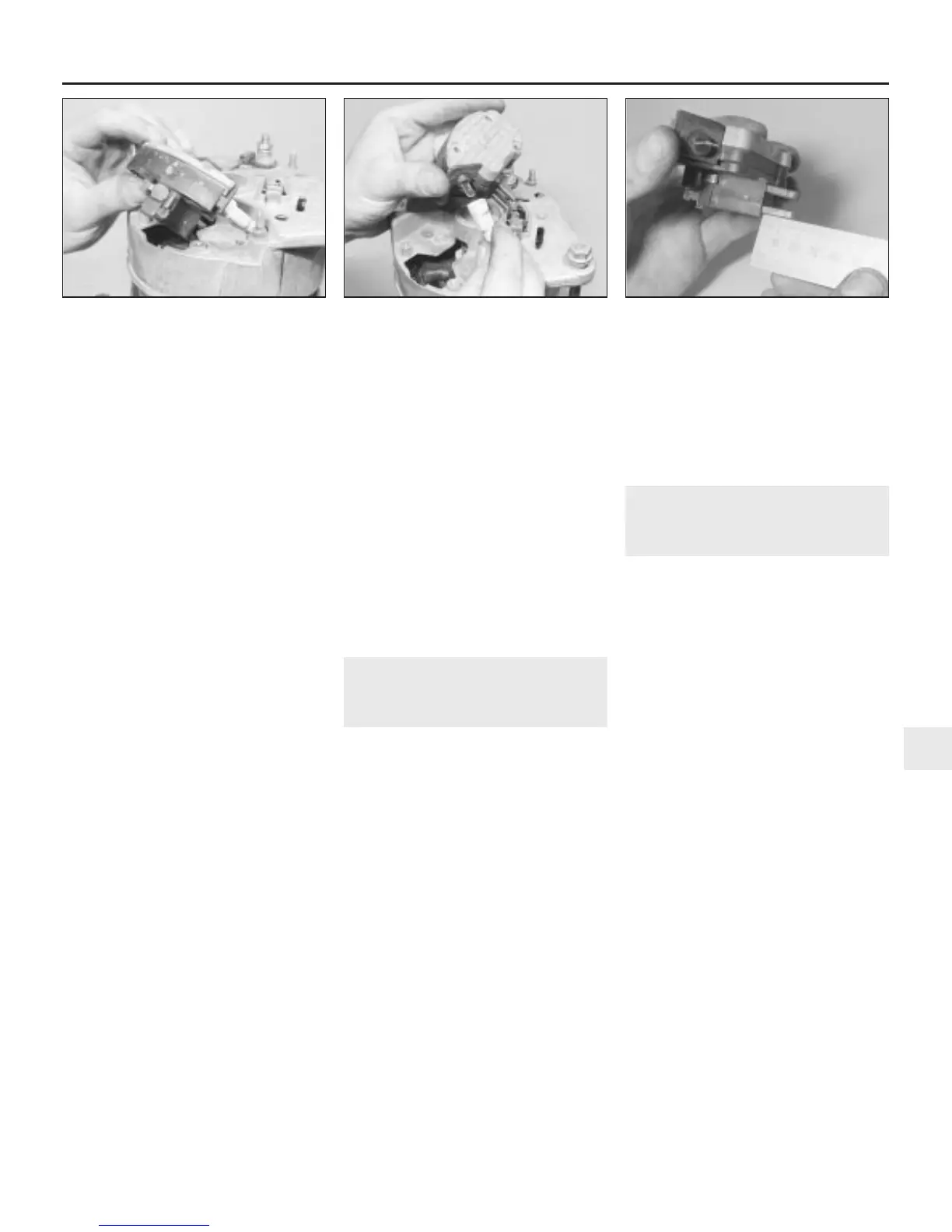
wiring terminal and remove the regulator and
brushbox from the alternator (see illustrations).
4 Measure the brush length and renew the
brushbox and regulator assembly if the
brushes are worn below the figure given in the
Specifications (see illustration).
5 Clean the slip rings with a solvent-
moistened cloth, then check for signs of
scoring, burning or severe pitting. If evident,
the slip rings should be attended to by an
automobile electrician.
6 Refitting is a reversal of removal.
A133 alternator - 4-cylinder
engines
7 Disconnect the lead then undo the bolt and
remove the suppression capacitor from the
alternator rear cover.
8 Undo the two retaining screws and remove
the rear cover from the alternator.
9 Disconnect the regulator leads, undo the
retaining screws and remove the regulator
from the brush box.
10 Undo the retaining screws and extract the
brushes from the brush box.
11 Undo the retaining screws and withdraw
the brush box from the slip ring end bracket.
12 Measure the brush length and renew the
brushes if worn below the figure given in the
Specifications.
13 Clean the slip rings with a solvent-
moistened cloth, then check for signs of
scoring, burning or severe pitting. If evident,
the slip rings should be attended to by an
automobile electrician.
14 Refitting is a reversal of removal.
A1271 alternator - 4-cylinder
engines
15 The A1271 alternator fitted to later models
is only serviced as a complete assembly. No
parts are available separately and repairs to
the unit are not possible.
CGK 46 alternator - V6 engines
16 Undo the nut, remove the washer and slip
off the insulator from the alternator main feed
terminal. Note the position of the insulator slot
for refitting.
17 Undo the three end cover retaining nuts
and remove the cover.
18 Undo the two brush holder retaining
screws and withdraw the brush holder
complete with brushes.
19 Undo the four regulator retaining screws
and withdraw the regulator from the rectifier
assembly. Note the screw lengths and their
locations for refitting.
20 Withdraw the brushes from the brush
holder and measure their lengths. Renew the
brushes if worn below the figure given in the
Specifications.
21 Clean the slip rings with a solvent-
moistened cloth, then check for signs of
scoring, burning or severe pitting. If evident,
the slip rings should be attended to by an
automobile electrician.
22 Refitting is a reversal of removal.
19 Starting system - general
information and precautions
General information
The starting system consists of the battery,
the starter motor, the starter solenoid, and the
wires connecting them. The solenoid is
mounted directly on the starter motor.
When the ignition key is turned to position
“III”, the starter solenoid is actuated through
the starter control circuit. The solenoid then
connects the battery to the starter. The
battery supplies the electrical energy to the
starter motor, which does the actual work of
cranking the engine.
The starter motor on a vehicle equipped
with automatic transmission can be operated
only when the selector lever is in Park or
Neutral (“P” or “N”).
Precautions
Always observe the following precautions
when working on the starting system:
(a) Excessive cranking of the starter motor
can overheat it, and cause serious
damage. Never operate the starter motor
for more than 15 seconds at a time
without pausing to allow it to cool for at
least two minutes. Excessive starter
operation will also risk unburned fuel
collecting in the catalytic converter’s
element, causing it to overheat when the
engine does start (see Chapter 4, Part E).
(b) Always detach the lead from the negative
terminal of the battery before working on
the starting system (see Section 1).
20 Starting system - testing
2
1 If the starter motor does not turn at all when
the switch is operated, make sure that, on
automatic transmission models, the selector
lever is in Park or Neutral (“P” or “N”).
2 Make sure that the battery is fully-charged,
and that all leads, both at the battery and starter
solenoid terminals, are clean and secure.
3 Check the condition of the relevant fuse
and fusible link, referring to Chapter 12 and
the wiring diagrams at the end of this manual
for further information.
4 If the starter motor spins but the engine is
not cranking, the overrunning clutch or (when
applicable) the reduction gears in the starter
motor may be slipping, in which case the
starter motor must be overhauled or renewed.
(Other possibilities are that the starter motor
mounting bolts are very loose, or that teeth
are missing from the flywheel ring gear.)
5 If, when the switch is actuated, the starter
motor does not operate at all but the solenoid
clicks, then the problem lies with either the
battery, the main solenoid contacts, or the
starter motor itself (or the engine is seized).
6 If the solenoid plunger cannot be heard to
click when the switch is actuated, the battery
is faulty, there is a fault in the circuit, or the
solenoid itself is defective.
7 The solenoid contacts can be checked by
connecting a voltmeter or test light between
the battery positive feed connection on the
starter side of the solenoid, and earth. When
the ignition switch is turned to the “start”
position, there should be a reading or lighted
bulb, as applicable. If there is no reading or
lighted bulb, the solenoid is faulty and should
be renewed.
Engine electrical systems 5•11
18.4 Checking alternator brush length18.3b . . . and disconnect the wiring18.3a Withdraw the regulator and
brushbox . . .
5
1380 Rover 800 Series Remake


 To Next Page
 Loading...
