3 Lower the jack slowly and carefully to
release the tension on the coil spring.
4 When all the tension is released, withdraw
the spring from its location, and recover the
upper and lower spring seats. Note the fitted
position of the lower seat in the transverse link
as it is removed.
5 Examine the spring carefully for signs of
distortion or damage. The spring free length
can only be assessed by comparing it with a
new item, and this should be done if the
spring is suspect. Renew the spring if
necessary, ideally in pairs (both sides). Also
check the condition of the upper and lower
spring seats, and renew any components as
necessary.
Refitting
6 Refitting is a reversal of removal, but ensure
that the tang on the lower spring seat
engages with the slot in the transverse link.
Tighten all nuts and bolts to the specified
torque, but do not fully tighten the transverse
and trailing link retaining nuts until the weight
of the car is on the roadwheels.
15 Transverse link -
removal and refitting
4
Removal
1 Remove the rear coil spring as described in
the previous Section.
2 Undo the nut and remove the transverse
link inner mounting bolt (see illustration).
3 Ease the link away from its inner location,
and remove it from under the car.
4 If the transverse link inner mounting bush
requires renewal, a hydraulic press and
mandrels will be needed to replace the bush.
If this equipment is not available, have the
work carried out by a Rover dealer or suitably-
equipped garage. A similar procedure must
be used for renewal of the outer bush, which
is located in the hub carrier, after removal of
this component from the car (see Section 11).
Refitting
5 Refitting is a reversal of removal, but do not
fully tighten the inner mounting nut until the
weight of the car is on the roadwheels.
16 Trailing link -
removal and refitting
4
Removal
1 Chock the front wheels, prise off the rear
wheel trim and slacken the wheel nuts. Jack
up the rear of the car and support it on axle
stands. Remove the rear roadwheel
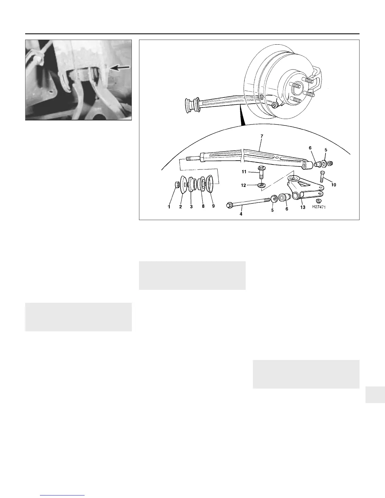
2 Undo the trailing link front mounting nut
and remove the outer washer and bush (see
illustration).
3 Undo the nut and remove the through-bolt
and washers securing the trailing link to the
hub carrier.
4 Ease the link away from the hub carrier,
withdraw the front mounting from its location
and remove the link from under the car.
5 Withdraw the front mounting inner bush
and washer, and the two rear mounting
bushes.
6 If the adjustment plate is to be removed,
first mark the position of the forward eccentric
bolt in relation to the plate, so that an
approximate rear wheel toe setting can be
obtained on reassembly. Undo the nuts,
remove the retaining bolt and eccentric bolt,
then withdraw the adjustment plate from the
trailing link.
7 Examine all the mounting bushes for
damage, deformation or swelling of the
rubber, and check the remaining components
for damage or distortion. Renew any parts as
necessary.
Refitting
8 Refit the adjustment plate to the link, and
secure with the retaining and adjustment bolts
and nuts. Before fully tightening the nuts, set
the eccentric adjustment bolt in the position
marked before removal.
9 The remainder of the refitting procedure is a
reversal of removal. Do not fully tighten the
trailing link-to-hub carrier through-bolt until
the weight of the car is on the roadwheels.
10 On completion, have the rear wheel
alignment checked and if necessary adjusted
(see Section 28).
17 Rear anti-roll bar -
removal and refitting
3
Removal
1 Apply the handbrake, prise off the rear
wheel trims and slacken the wheel nuts. Jack
up the rear of the car and support it on axle
stands. Remove the rear roadwheels.
2 Undo the single nut each side securing the
anti-roll bar connecting links to the rear
suspension transverse links.
3 Undo the two bolts each side securing the
anti-roll bar mounting brackets to the chassis
Suspension and steering systems 10•11
16.2 Trailing link components and attachments
15.2 Transverse link inner mounting bolt
(arrowed)
10
1380 Rover 800 Series Remake
1 Front mounting nut
2 Outer washer
3 Outer bush
4 Trailing link through-bolt
5 Washer
6 Bush
7 Trailing link
8 Inner bush
9 Inner washer
10 Adjustment
plate
retaining bolt
11 Eccentric bolt
12 Eccentric washer
13 Adjustment plate


 To Next Page
 Loading...
