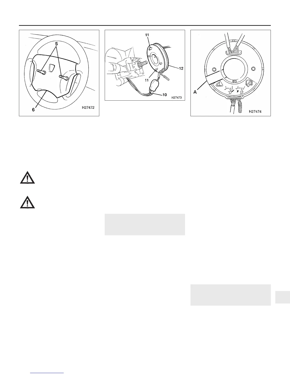
two airbag module retaining screws from the
rear of the steering wheel (see illustration).
18 Lift the airbag module off the steering
wheel, disconnect the multiplug from the rear
of the module and remove the module from
the vehicle.
Warning: Position the airbag
unit in a safe place, with the
mechanism facing downwards
as a precaution against
accidental operation.
Warning: Do not attempt to
open or repair the airbag unit, or
apply any electrical current to it.
Do not use any airbag which is
visibly damaged or which has been
tampered with.
19 Set the front wheels in the straight-ahead
position.
20 On models equipped with cruise control,
disconnect the cruise control switch multiplug
from the rotary coupler wiring harness and
release the harness from the steering wheel
clip.
21 With an assistant holding the wheel, undo
and remove the centre retaining nut using a
socket and bar.
22 Mark the steering wheel and column shaft
in relation to each other, and withdraw the
wheel from the shaft splines.
23 On models with cruise control, feed the
wiring harness through the hole in the steering
wheel as it is withdrawn.
Refitting
24 Check that the front wheels are still in the
straight-ahead position, then engage the
steering wheel over the shaft splines, while at
the same time feeding the wiring harness
through the hole in the wheel. Ensure that the
previously-made marks are aligned, and that
the rotary coupler lugs engage with the
steering wheel slots.
25 Refit the retaining nut and tighten it to the
specified torque while your assistant holds the
wheel.
27 Reconnect the cruise control wiring
(where applicable).
28 Reconnect the wiring multiplug to the rear
of the airbag module with the harness pointing
downward.
29 Locate the airbag module on the steering
wheel and secure with the two retaining
screws.
30 Reconnect the airbag wiring multiplug to
the steering column wiring harness and refit
the fusebox cover.
31 Reconnect the battery.
19 Rotary coupler -
removal and refitting
3
Removal
1 A rotary coupler is fitted between the
steering wheel and steering column
multifunction switch on vehicles equipped
with an airbag supplementary restraint system
and/or cruise control.
2 Remove the steering wheel as described in
Section 18.
3 From inside the car, release the turnbuckles
and lift out the trim panels over the clutch,
brake and accelerator pedals.
4 Release the rake lock on the side of the
steering column, and move the column to its
lowest position.
5 Undo the single upper screw and the three
lower screws, and remove the upper and
lower steering column shrouds.
6 Disconnect the rotary coupler multiplug
from the steering column wiring harness (see
illustration). On models equipped with an
airbag, release the airbag wiring harness
connector from the steering column bracket
and remove the harness cable ties from the
column.
7 Ensure that the front roadwheels are in the
straight-ahead position then release the two
plastic clips and withdraw the coupler from
the steering column multifunction switch.
Note: The rotary coupler must not be turned
whilst it is removed. To prevent rotation of the
two coupler halves, place a piece of adhesive
tape around the moulding as shown (see
illustration). Store the coupler in a plastic bag
after removal as an added precaution against
rotation or damage.
Refitting
8 Refitting is a reversal of removal bearing in
mind the following points:
(a) If a new rotary coupler is being fitted it will
be supplied with sealing tape around the
moulding to prevent rotation of the
coupler halves. Do not use the coupler if
the sealing tape is broken.
(b) If the original rotary coupler is being
refitted, remove the previously applied
adhesive tape before positioning the unit
on the steering column.
(c) Use new cable ties to secure the wiring
harness to the steering column.
(d) Refit the steering wheel as described in
Section 18.
20 Steering column lock -
removal and refitting
3
Removal
1 Remove the steering wheel as described in
Section 18.
2 From inside the car, release the turnbuckles
and lift out the trim panels over the clutch,
brake and accelerator pedals.
3 Release the rake lock on the side of the
Suspension and steering systems 10•13
19.7 After removal, secure the two halves
of the rotary coupler to prevent rotation,
using adhesive tape applied to position (A)
19.6 Rotary coupler connections on
models with airbag supplementary
restraint system and/or cruise control
10 Rotary coupler multiplug
11 Plastic retaining clips
12 Rotary coupler
18.17 Unscrew the two retaining
screws (5) securing the airbag (6) to the
steering wheel
10
1380 Rover 800 Series Remake


 To Next Page
 Loading...
