the crankshaft one turn clockwise, then one
turn anti-clockwise. It must be emphasised
that this is only an approximate setting, and
the tension should be checked by a dealer,
using the Rover tension gauge, at the earliest
opportunity.
52 The remainder of refitting is a reversal of
removal.
8 Timing belt (“T” series) -
removal, refitting and
adjustment
4
Removal
1 Disconnect the battery negative (earth) lead
(refer to Chapter 5, Section 1).
2 Slacken the right-hand front wheel nuts,
jack up the front of the car and support it on
axle stands. Remove the roadwheel.
3 Undo the three bolts and remove the
access panel under the wheelarch.
4 Refer to Chapter 1 and remove the auxiliary
drivebelt.
5 Position a jack and interposed block of
wood under the sump, and just take the
weight of the engine.
6 Undo the bolts securing the power steering
pipe support brackets, and move the pipes
slightly to gain access to the right-hand
engine mounting.
7 Undo the engine mounting through-bolt,
and recover the special nut. Note that the
forked end of the nut plate locates over a stud
on the body bracket.
8 Undo the two bolts securing the engine
mounting to its mounting bracket, and remove
the mounting.
9 Raise the engine slightly, then undo the five
bolts and lift off the timing belt upper cover
(see illustration).
10 Undo the remaining five bolts and remove
the timing belt centre cover.
11 Using a socket or spanner on the
crankshaft pulley, turn the crankshaft in an
anti-clockwise direction until the timing
notches on the camshaft sprockets are facing
each other and aligned horizontally. Insert a
dowel rod or drill through the hole in the
transmission adaptor plate, near to the lower
edge of the cylinder block on the front-facing
side of the engine (see illustration 7.12). The
dowel or drill will then engage with a
corresponding hole in the flywheel. If the
dowel won’t engage, turn the crankshaft
through 180º and try again.
12 With the dowel rod engaged and the
camshaft notches aligned, the crankshaft is at
90º BTDC, with No 1 piston on its
compression stroke. Temporarily remove the
dowel rod.
13 Refer to Chapter 5, and remove the starter
motor.
14 Using a socket and long handle, slacken
the crankshaft pulley centre retaining bolt.
Lock the flywheel ring gear, through the
starter motor aperture, using a large
screwdriver or similar tool to prevent the
crankshaft rotating as the pulley bolt is
undone. This operation will probably have
moved the timing marks on the camshafts out
of alignment, so re-align them, and fit the
crankshaft dowel rod as described previously.
15 Remove the centre retaining bolt from the
crankshaft pulley, then unscrew the four
additional pulley bolts and remove the pulley.
16 Undo the three bolts and remove the
timing belt bottom cover.
17 Slacken the timing belt tensioner centre
bolt, move the tensioner away from the belt as
far as it will go, then re-tighten the tensioner
bolt.
18 Slip the belt off the sprockets, and
remove it from the engine.
19 If the timing belt is to be re-used, mark its
running direction with an arrow in chalk, and
store it on its edge while it is off the engine.
20 Check the tensioner and sprockets as
described in Section 9.
Refitting and adjustment
21 Before refitting the belt, check that the
crankshaft is still at the 90º BTDC position
(dowel rod engaged) and that the timing
marks on the two sprockets are still aligned.
22 Engage the timing belt with the teeth of
the crankshaft sprocket, and then pull the belt
vertically upright on its straight, right-hand
run. Keep it taut, and engage it over the
exhaust camshaft sprocket, then the inlet
camshaft sprocket.
23 Check that none of the sprockets have
moved, then feed the belt around the
tensioner.
24 Refit the timing belt bottom cover.
25 Remove the dowel rod from the
crankshaft.
26 Refit the crankshaft pulley and secure
with the centre bolt and four additional bolts,
tightened to the specified torque. Hold the
crankshaft using the same procedure as for
removal to tighten the centre bolt.
27 Slacken the timing belt tensioner retaining
bolt slightly and allow the tensioner to
automatically tension the belt.
28 Using a torque wrench applied to the inlet
camshaft sprocket retaining bolt, apply a load
of 40 Nm, in an anti-clockwise direction, to
take up all the slack in the timing belt. Hold
this load, and tighten the tensioner retaining
bolt to the specified torque.
29 The remainder of refitting is a reversal of
removal.
4-cylinder engine – in-car engine repair procedures 2A•9
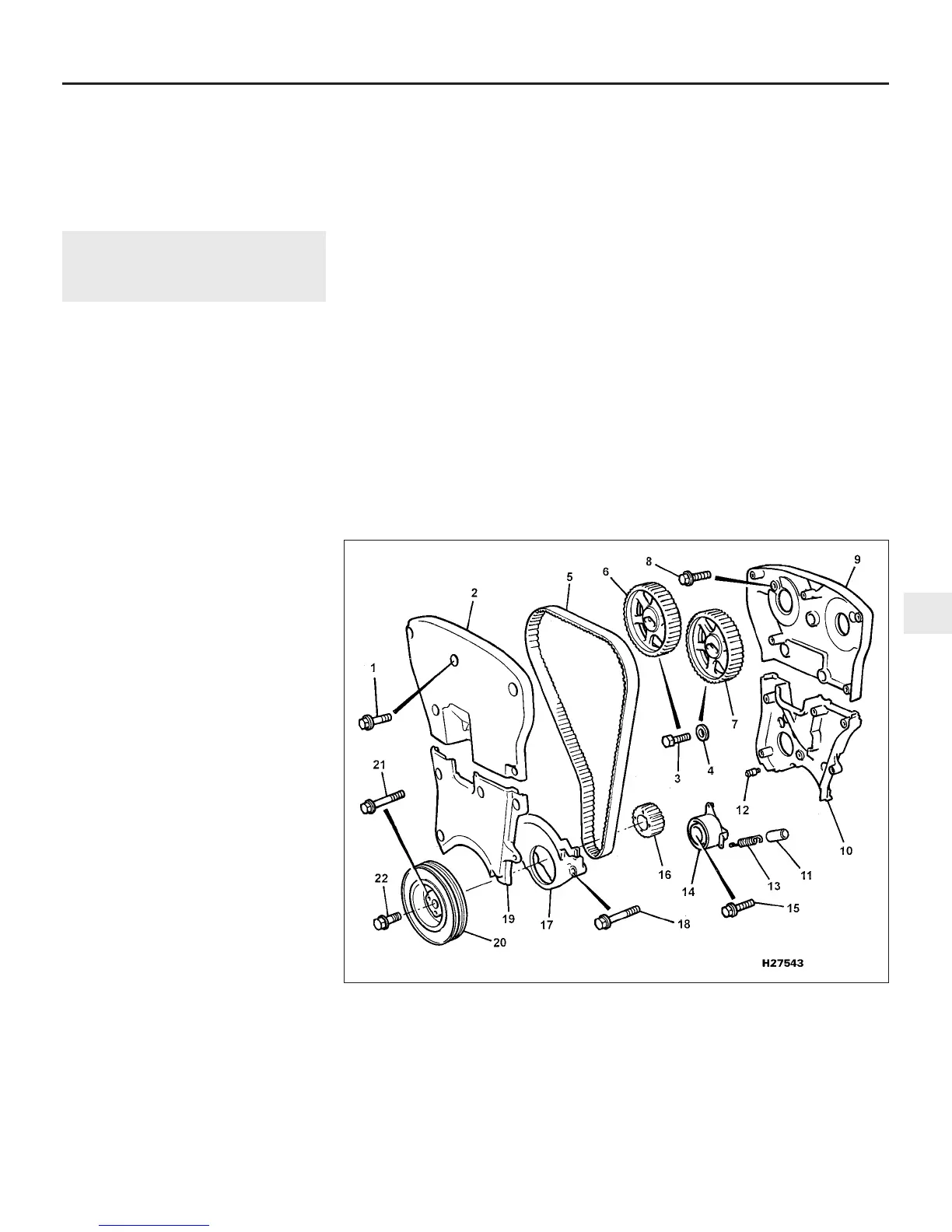
8.9 Timing belt components as fitted to “T” series engines
1 Upper cover bolt
2 Upper cover
3 Camshaft sprocket bolt
4 Washer
5 Timing belt
6 Inlet camshaft sprocket
7 Exhaust camshaft sprocket
8 Backplate bolt
9 Upper backplate
10 Lower backplate
11 Spring sleeve
12 Anchorage bolt
13 Tensioner spring
14 Timing belt tensioner
15 Tensioner bolt
16 Crankshaft sprocket
17 Bottom cover
18 Bottom cover bolt
19 Centre cover
20 Crankshaft pulley
21 Pulley-to-sprocket bolts
22 Pulley centre bolt
2A
1380 Rover 800 Series Remake
 Loading...