arm spacer springs and the rocker arms, and
place them in their appropriate compartments
of the marked box that has all the hydraulic
tappets and slippers removed previously.
Alternatively use labelled plastic bags.
6 Undo the eight bolts securing the guide
plates and lift the guide plates off their
locating dowels.
7 To remove the valves, compress each
spring in turn with a universal valve spring
compressor, until the two retaining collets can
be removed.
8 Release the compressor, and lift off the
spring top cup, valve spring(s), oil seal, valve
spring seat and the valve.
9 It is essential that the valves are kept in
their correct order, unless they are so badly
worn or burnt that they are to be renewed. If
they are going to be refitted, place them in
their correct sequence, along with the tappets
and other parts removed previously. Also
keep the valve springs, cups, seats and
collets in the same order.
9 Cylinder head, rocker gear
and valve assemblies -
cleaning and inspection
4
Note: Always check first what replacement
parts are available before planning any
overhaul operation. A Rover dealer, or a good
engine reconditioning specialist/automotive
parts supplier, may be able to suggest
alternatives which will enable you to overcome
the lack of replacement parts.
1 Thorough cleaning of the cylinder head and
valve components, followed by a detailed
inspection, will enable you to decide how
much valve service work must be carried out
during the engine overhaul. Note: If the
engine has been severely overheated, it is best
to assume that the cylinder head is warped,
and to check carefully for signs of this.
Cleaning
2 Scrape away all traces of old gasket
material and sealing compound from the
cylinder head.
3 Scrape away the carbon from the
combustion chambers and ports, then wash
the cylinder head thoroughly with paraffin or
solvent.
4 Scrape off any heavy carbon deposits that
may have formed on the valves, then use a
power-operated wire brush to remove
deposits from the valve heads and stems.
Inspection
Note: Be sure to perform all the following
inspection procedures before concluding that
the services of a machine shop or engine
overhaul specialist are required. Make a list of
all items that require attention.
Cylinder head
5 Inspect the head very carefully for cracks,
evidence of coolant leakage, and damage. If
cracks are found, a new cylinder head should
be obtained.
6 Use a straight edge and feeler blade to
check that the head gasket surface is not
distorted. If it is, it may be possible to re-
surface it.
7 Examine the valve seats in each of the
combustion chambers. If they are severely
pitted, cracked or burned, then they will need
to be renewed or re-cut by an engine overhaul
specialist. If they are only slightly pitted, this
can be removed by grinding-in the valve
heads and seats with fine valve-grinding
compound, as described below.
8 If the valve guides are worn, indicated by a
side-to-side motion of the valve, new guides
must be fitted. Measure the diameter of the
existing valve stems (see below) and the bore
of the guides, then calculate the clearance,
and compare the result with the specified
value; if the clearance is excessive, renew the
valves or guides as necessary.
9 The renewal of valve guides is best carried
out by an engine overhaul specialist.
10 If the valve seats are to be re-cut, this
must be done only after the guides have been
renewed.
Valves
11 Examine the head of each valve for
pitting, burning, cracks and general wear, and
check the valve stem for scoring and wear
ridges. Rotate the valve, and check for any
obvious indication that it is bent. Look for pits
and excessive wear on the tip of each valve
stem. Renew any valve that shows any such
signs of wear or damage.
12 If the valve appears satisfactory at this
stage, measure the valve stem diameter at
2C•10 Engine removal and general engine overhaul procedures
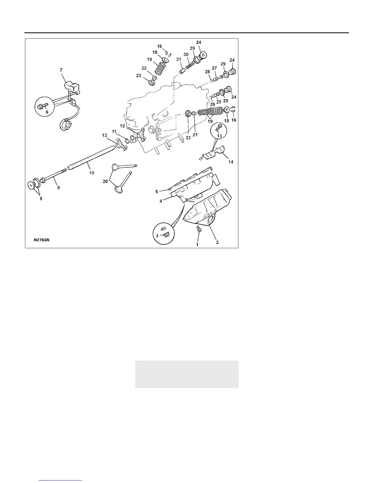
8.2 V6 engine cylinder head and rocker gear components
1 Exhaust manifold heat
shield bolt
2 Exhaust manifold heat
shield
3 Manifold nut
4 Exhaust manifold
5 Gasket
6 Crank/angle sensor bolts
7 Crank/angle sensor
8 Blanking plug and seal
9 Bolt for rocker shaft
removal
10 Rocker shaft
11 Spacer springs
12 Rocker arm
13 Guide plate bolts
14 Guide plates
16 Collets
18 Spring top cups
19 Valve springs
20 Valves
22 Oil seal
23 Spring seats
24 Blanking plugs
25 Oil restrictor
26 O-ring
27 Oil plug
28 O-ring
29 Blanking plugs
30 Spring
31 Relief valve
1380 Rover 800 Series Remake
 Loading...