21 Undo the three bolts and remove the
thermostat housing and gasket.
22 Withdraw the thermostat from its seat in
the housing.
Testing
23 Refer to the procedures described above
for 4-cylinder engines.
Refitting
24 Refitting is a reversal of removal. Ensure
that the housing mating surfaces are clean
and use a new gasket.
5 Electric cooling fan
assembly - testing, removal
and refitting
5
Note: Refer to the warnings given in Section 1
of this Chapter before starting work.
Note: On cars equipped with air conditioning,
a second cooling fan for the condenser is
mounted alongside the main cooling fan for
the radiator The following procedures are
applicable to both types of installation.
Testing
1 The cooling fans are controlled by complex
circuitry and their operation is dependant on a
number of factors. Single or twin fans may be
fitted, with variable speed operation.
Numerous sensors used in conjunction with
the engine management system and, where
fitted, the air conditioning system determine
their operating temperature and at what
speed they will run.
2 If it is suspected that the cooling fan(s) are
not operating when high engine temperature
would normally require them to do so, check
the relevant fuses and relays (see Chapter 12)
and ensure that all wiring connections are
clean and soundly made.
3 Further testing can really only be carried out
successfully using Rover test equipment and
should therefore be entrusted to a dealer.
Removal
4 On pre-1992 model year vehicles, remove
the radiator grille as described in Chapter 11,
Section 19.
5 On turbocharged and V6 engines, remove
the engine undertray.
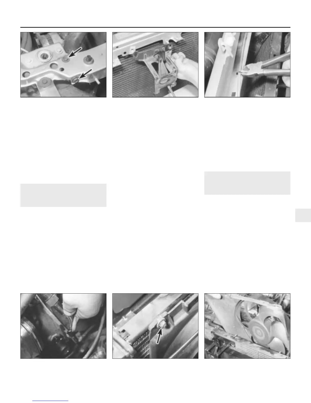
6 Undo the two bolts each side securing the
centre platform to the body side members
(see illustration).
7 Undo the nut and retaining bolt securing
the bonnet safety catch to the centre platform
(see illustration).
8 Lift the centre platform upwards, turn it
over, and cut off the cable ties securing the
bonnet release cable to the platform
underside (see illustration). Remove the
platform from the car.
9 Disconnect the cooling fan multiplug at the
wiring connector (see illustration).
10 Undo the three retaining nuts (four on
turbocharged engines), then carefully lift out
the cooling fan assembly (see illustrations).
Note that the cooling fan, motor and cowl are
a balanced assembly, and should not be
dismantled. Should renewal be necessary, all
three components are supplied as an
assembled unit.
Refitting
11 Refitting is a reversal of removal.
6 Cooling system electrical
switches and sensors -
removal and refitting
1
Note: Refer to the warnings given in Section 1
of this Chapter before starting work.
Cooling fan thermostatic switch
Note: On cars equipped with air conditioning,
a second thermostatic switch for the
condenser fan is mounted in the radiator side
tank, below the main thermostatic switch for
the radiator cooling fan. The following
procedures are applicable to both types of
installation.
Removal
1 Partially drain the cooling system
(approximately 2.5 litres), as described in
Chapter 1
2 Disconnect the two wires, remove the
switch retaining ring, which is a bayonet
Cooling, heating and air conditioning systems 3•5
5.8 Cut off the cable ties securing the
bonnet release cable
5.7 Remove the bonnet safety catch from
the centre platform
5.6 Centre platform retaining bolts - right-
hand side (arrowed)
5.10b Removing the cooling fan assembly5.10a Cooling fan upper retaining nut
(arrowed)
5.9 Disconnect the cooling fan multiplug
at the wiring connector
3
1380 Rover 800 Series Remake


 To Next Page
 Loading...
