MAINTENANCE
THROTTLE
CONTROL:
CUTTING
UNIT
DRIVE
ADJUSTMENT:
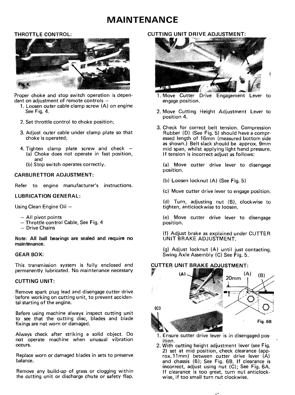
Proper choke and stop switch
operation
is depen-
dant on adjustment
of
remote
controls
~
1. Loosen
outer
cable clamp screw
(A)
on engine
See
Fig. 4.
2.
Set
throttle
control
to
choke
position;
3. Adjust
outer
cable under clamp plate so
that
choke is operated;
4. Tighten clamp plate screw and check -
(a) Choke does
not
operate in fast
position,
and
(b) Stop switch operates
correctly.
CARBURETTOR
ADJUSTMENT:
Refer
to
engine manufacturer's instructions.
LUBRICATION
GENERAL:
Using Clean Engine Oil -
-
All
pivot
points
-
Throttle
control
Cable, See Fig. 4
-- Drive Chains
Note:
All
ball bearings are sealed and require no
maintenance.
GEAR BOX:
This transmission system is
fully
enclosed and
permanently lubricated. No maintenance necessary
CUTTING
UNIT:
Remove spark plug lead and disengage
cutter
drive
. before working on
cutting
unit,
to
prevent acciden-
tal starting
of
the
engine.
Before using machine always inspect
cutting
unit
to
see
that
the
cutting
disc, blades and blade
fixings are
not
worn
or
damaged.
Always check after
striking
a solid object. Do
not
operate machine when unusual
vibration
occurs.
Replace worn or damaged blades in sets
to
preserve
balance.
Remove any build-up
of
grass or clogging
within
the
cutting
unit
or discharge
chute
or
safety flap.
1. Move
Cutter
Drive Engagement Lever
to
engage
position.
2. Move
Cutting
Height
Adjustment
Lever
to
position
4.
3.
Check
for
correct
belt
tension. Compression
Rubber (D) (See Fig.
5) should have a
compr-
essed
length
of
16mm
(measured
bottom
side
as shown.)
Belt
slack should be
approx.
9mm
mid
span,
whilst
applying
Ijght
hand pressure.
If
tension is
incorrect
adjust as
follows:
(a) Move
cutter
drive lever
to
disengage
position.
(b) Loosen
locknut
(A)
(See Fig. 5)
(c) Move
cutter
drive
lever
to
engage position.
(d)
Turn,
adjusting
nut
(B), clockwise
to
tighten,
anticlockwise
to
loosen.
(e) Move
cutter
drive
lever
to
disengage
position.
(f)
Adjust
brake as explained
under
CUTTE
R
UNIT
BRAKE
ADJUSTMENT.
(g)
Adjust
locknut
(A)
until
just
contacting.
Swing
Axle
Assembly (C) See Fig. 5.
CUTTER
UNIT
BRAKE
ADJUSTMENT:
,
-~)
~)
(e)
Fig.
68
1. Ensure
cutter
drive lever is in disengaged pos-
ition.
2.
With
cutting
height
adjustment
lever
(see
Fig.
2) set at
mid
position,
check clearance (app-
rox.
11
mm)
between
cutter
drive lever (A)
and chassis
(B);
See Fig. 6B.
If
clearance is
incorrect, adjust using
nut
(C); See Fig.
6A.
If
clearance is
too
great,
turn
nut
anticlock-
wise,
if
too
small
turn
nut
clockwise.