ENGINE K SERIES 1.8 VVC
Technical Academy
01-34-RG-W-Ver:1 Page 15 of 28
• Carefully release the camshaft carrier from the cylinder head, then lift the carrier from
the cylinder head complete with the VVC assemblies.
• Ensure that both inlet camshafts are retained in the carrier, then invert the assembly
• Slacken, but do not remove the 2 bolts securing the VVC housings to the carrier.
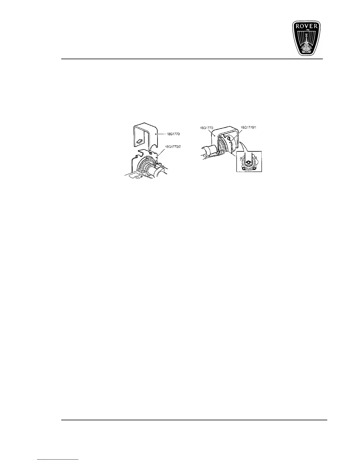
IMPORTANT: Sufficiently slacken the 2 bolts to enable the timing plates 18G 1770/1 and
18G 1770/2 to be fitted.
Figure 14
• Fit timing plates 18G 1770/1 to front and 18G 1770/2 to rear VVC assemblies, then fit
clamps 18G 1770, to both assemblies, securing the clamps with the camshaft gear
retaining bolts and washers.
CAUTION: Identify each VVC assembly in its fitted position an DO NOT attempt to
interchange the front and rear assemblies.
• Remove the 2 VVC housing bolts to the carrier, then carefully remove both camshafts
together with the VVC assemblies, but DO NOT remove clamps 18G 1770.
NOTE: Keep the 2 VVC housing bolts to carrier at this stage for assembly purposes.
New ‘Patchlock’ bolts will be fitted on final assembly.
• Remove the control shaft from the carrier and lift out the exhaust camshaft from the
cylinder head, then using a stick magnet, remove the hydraulic tappets keeping them in
their fitted order and inverted to prevent oil loss.
 Loading...