ENGINE K SERIES 1.8 VVC
Technical Academy
01-34-RG-W-Ver:1 Page 17 of 28
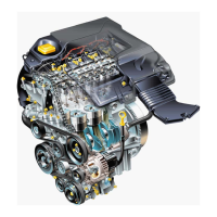
Figure 16
• Place a strip of Plastigage across each inlet camshaft journal, then carefully fit the
carrier to the cylinder head, securing the carrier with the 32 bolts, (4 longer bolts at each
end of carrier), and tighten in the sequence shown to 10Nm.
Figure 17
CAUTION: DO NOT rotate camshafts.
• Progressively slacken and remove bolts, then carefully remove camshaft carrier and
VVC assembly from the cylinder head ensuring that both inlet camshaft assemblies are
retained in their respective VVC assemblies, and the exhaust camshaft remains in the
cylinder head.
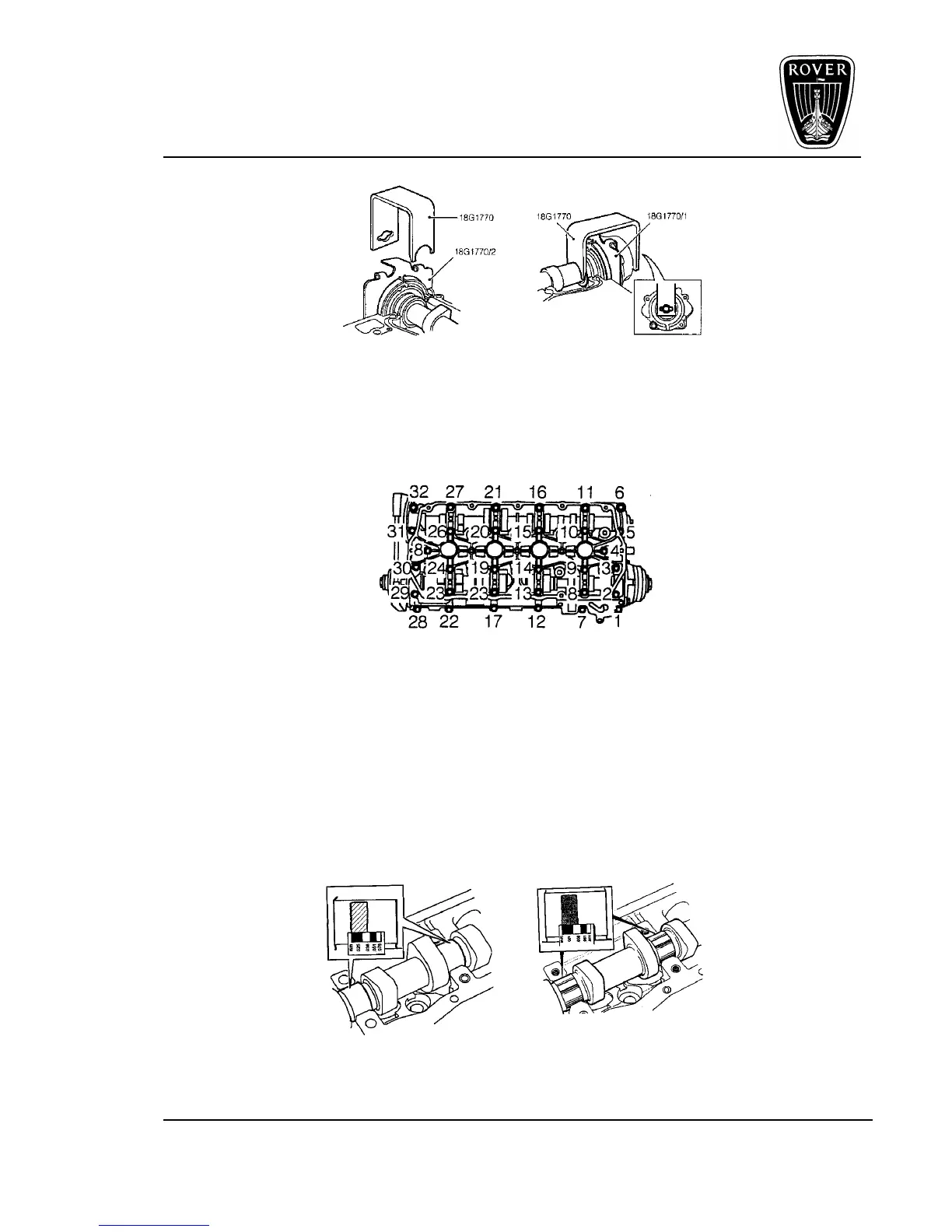
• Invert the carrier assembly and measure the widest portion of Plastigage on each inlet
camshaft journal and record measurement.
Inlet camshaft Exhaust camshaft
Figure 18
 Loading...