ENGINE K SERIES 1.8 VVC
Technical Academy
01-34-RG-W-Ver:1 Page 3 of 28
Designing a working system for a 4 cylinder 16 valve engine was somewhat more
complex! Accepting that all four pairs of camshaft lobes are positioned differently to cope
with their unique role in the four stroke cycle, then each pair must be controlled with a
degree of independence.
To achieve this, two VVC mechanisms are positioned either end of the cylinder head, each
controlling an inlet camshaft assembly; each of these assemblies drives two semi-
independent camshafts, one for each pair of valves, making four inlet camshafts in all.
As there is no direct drive between the two inlet camshaft assemblies, an additional drive
belt is used, transmitting drive from the back of the exhaust camshaft to the rear inlet cam
assembly.
A control shaft is used to transmit drive to both VVC mechanisms, this is in turn controlled
by a hydraulic rack driven by the Hydraulic Control Unit (HCU), the position of which is
monitored and controlled by the MEMS 2J ECM through two solenoid valves and a
camshaft period sensor. The main ECM inputs for VVC are engine speed and load.
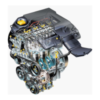
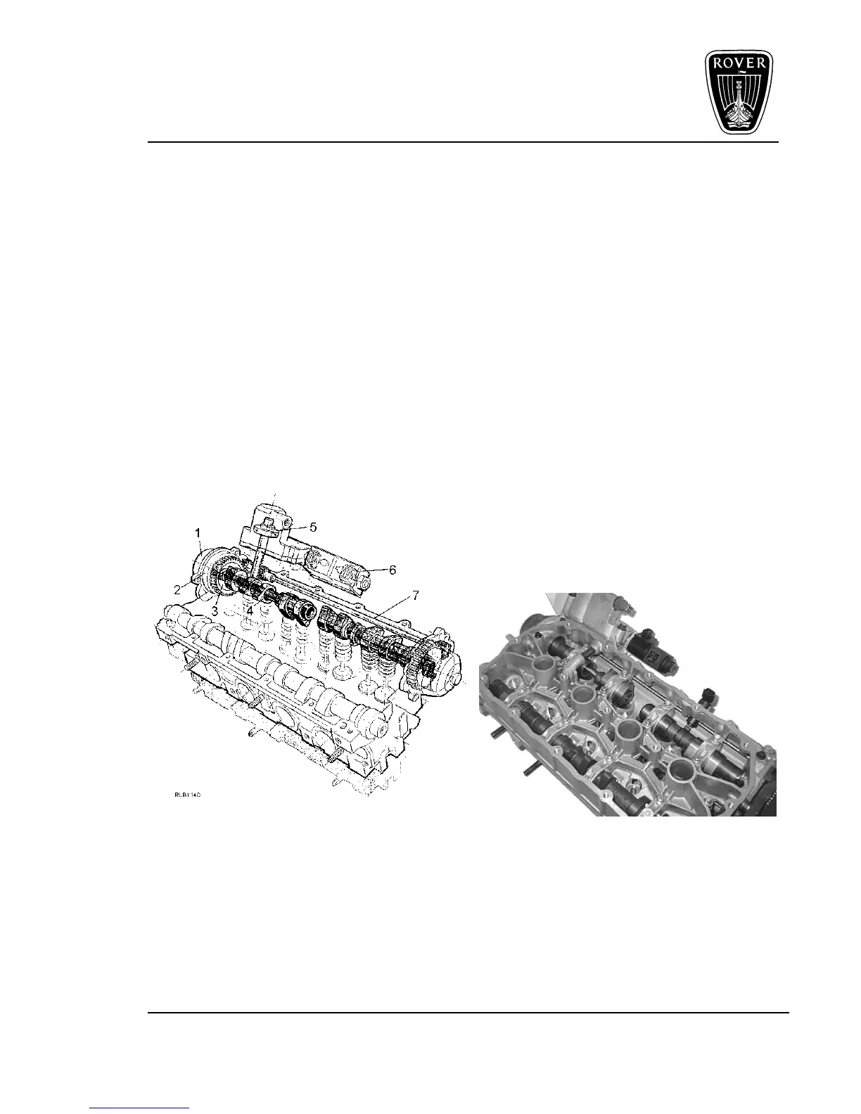
Figure 3
1. Camshaft drive 5. Piston
2. Control sleeve 6. HCU solenoids
3. Drive ring 7. Control shaft
4. Independent shaft
 Loading...