ENGINE K SERIES 1.8 VVC
Technical Academy
01-34-RG-W-Ver:1 Page 5 of 28
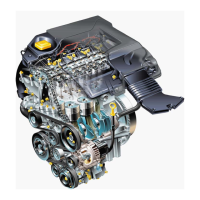
The following illustration shows the engine compartment components
for the 1.8 VVC MG-F.
Figure 5
1. Fuel filter 14. Manifold absolute pressure sensor
2. Resonator 15. Throttle cable
3. Fuel pump 16. Oil temperature sensor
4. Air filter 17. Ignition coil
5. Throttle position sensor 18. Fuel rail
6. Engine coolant temperature sensor 19. Idle air control valve
7. Intake air temperature sensor 20. Crankshaft position sensor
8. Camshaft position sensor 21. Throttle body
9. Oxygen sensor 22. Evaporative emission canister, purge valve
10. Injector (4 off) 23. Evaporative emission canister
11. Hydraulic control solenoids 24. Engine management relay module
12. Hydraulic control unit 25. Engine control module
13. Fuel pressure regulator 26. Inertia fuel shut-off switch
 Loading...