4
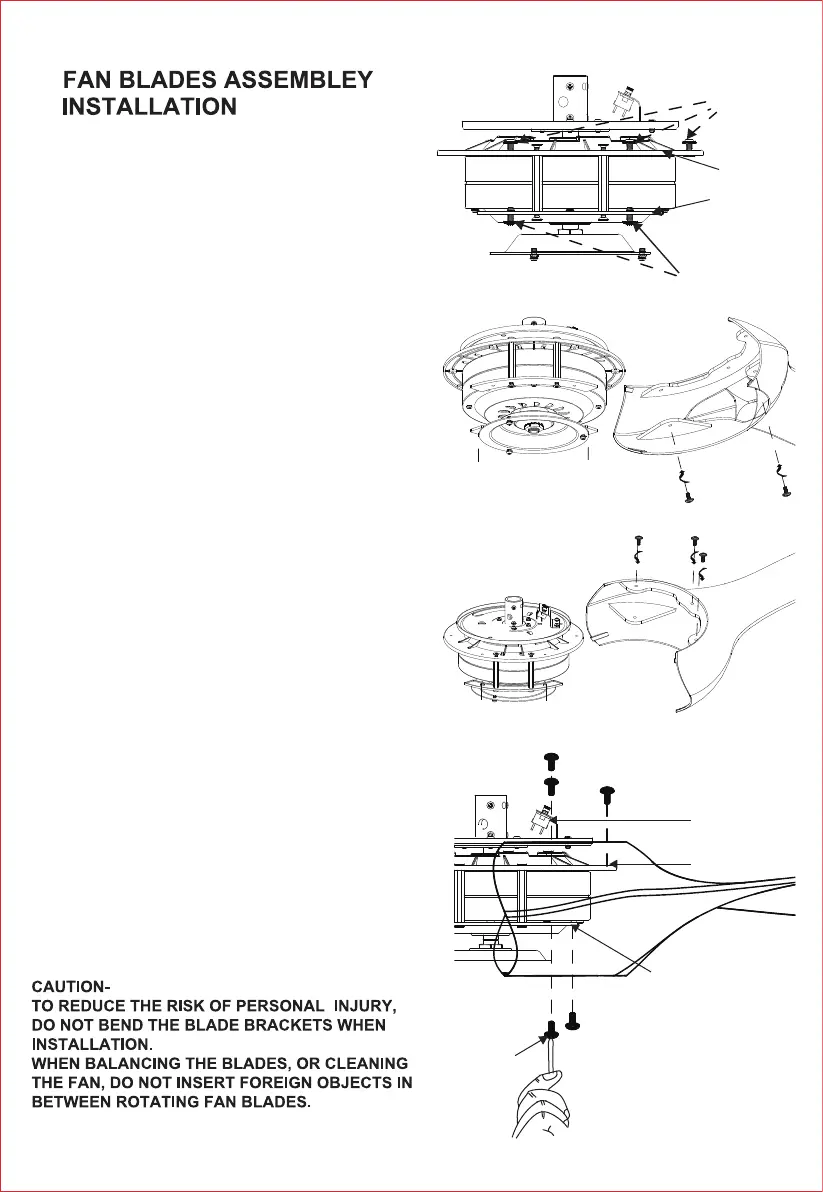
Step 1. Remove the 10 pcs screws on the blade bracket.
(upper bracket and lower bracket). (Fig.5.1)
5.
Figure 5.3
Screws
Bracket
Bracket
Reverse switch
B1B2
Step 2. Align the installation holes A1 to A1, A2 to A2,
A3 to A3; B1 to B1, B2 to B2. (The bracket and blade
have marked the A1,A2,A3; B1, B2 beside the installation
holes) . (Fig.5.2)
Step 3. Fix the two blades on the bracket using these
(10 pcs) screws. (Fig.5.3)
Upper bracket
Lower bracket
4 pcs screws on
the lower bracket
6 pcs screws
on the upper
bracket
B1
B1
B2
B1
B2
B2
A1
A2
A3
Installation hole
Installation hole
Blade A
B2
B1B1
Figure 5.1
Figure 5.2
Blade
A1
A2
A3