Do you have a question about the RS PRO Iso-tech IPS 303A and is the answer not in the manual?
Identify conditions or practices that could result in injury or loss of life.
Identify conditions or practices that could result in damage to this product or other property.
Main supply, rating, dimension, weight, operation mode, temperature, altitude, category, degree, indoor use, accessories.
Output voltage ranges, voltage regulation, recovery time, ripple & noise, temperature coefficient.
Output current range, current regulation, ripple & noise.
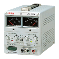
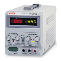
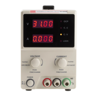
Details of front panel controls and indicators including CV/CC indicators, voltage/current controls, terminals, meter, and switches.
Details of rear panel components including fuse holder, power cord, AC selector, and master-slave switch.
Safety precautions for AC input, installation environment, and output voltage overshoot.
Procedure to set the current limit using coarse/fine controls and ammeter.
Explanation of the automatic crossover between constant voltage and constant current modes.
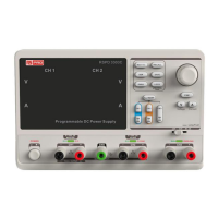
Instructions for single operation and series connection of two power supplies.
Procedure for connecting two power supplies in parallel for higher current output.
Procedure for remote voltage control using an external voltage source.
Procedure for remote current control using an external voltage source.
Information on dynamic load function and its suitability for audio circuitry testing.
Procedure and safety warnings for replacing a blown fuse.
Steps to change the unit's line voltage setting and potential fuse value change.
Guidance on when and how to perform internal adjustments using a multimeter.
Instructions for cleaning the power supply using mild detergent and water.
| Brand | RS PRO |
|---|---|
| Model | Iso-tech IPS 303A |
| Category | Power Supply |
| Language | English |